
MassArt Canopy Complete

Kurgo Container Project Complete


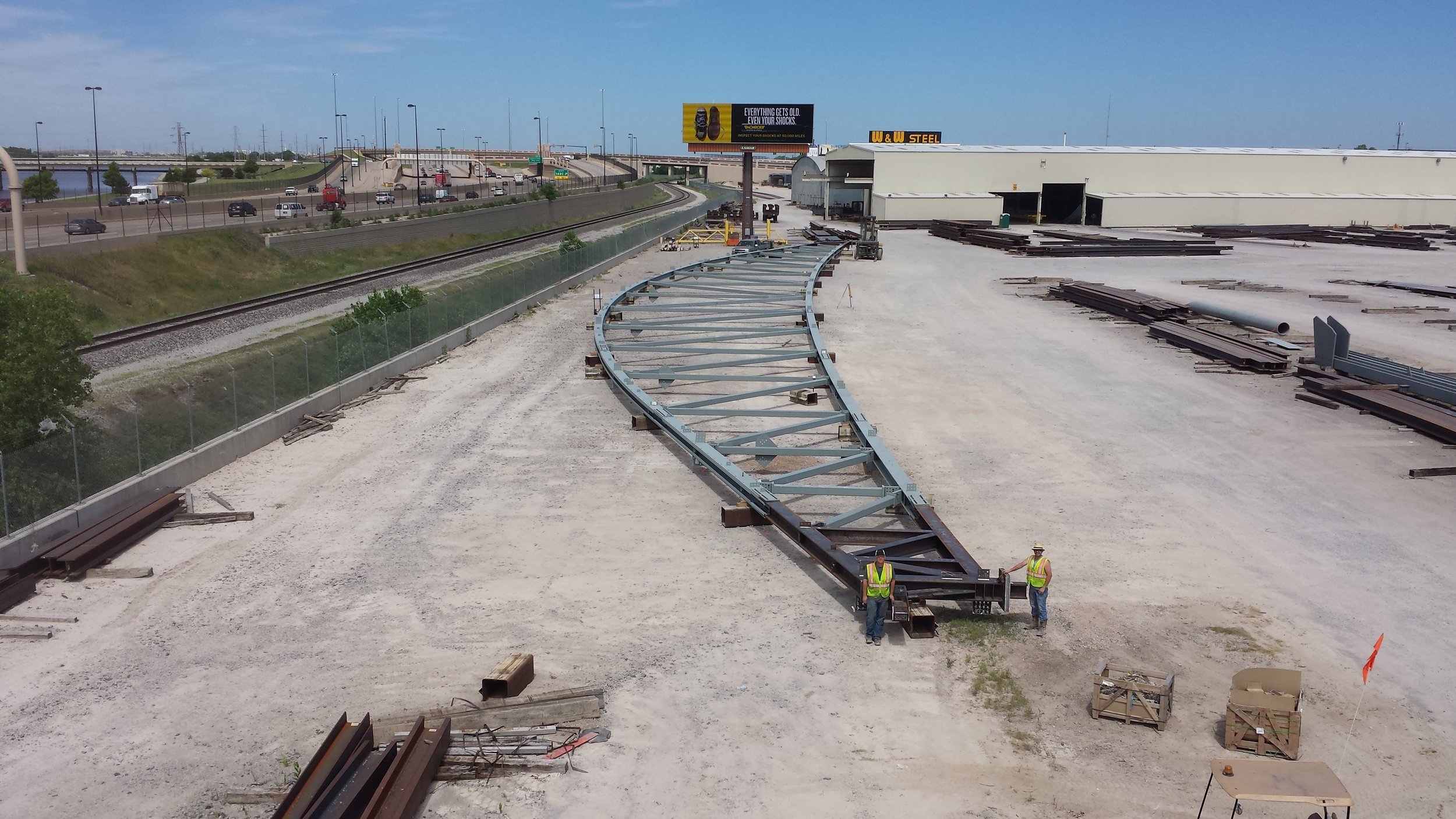
Trusses at Cowboy's Practice Field - In Contruction


34th Annual Steel Conference Speaker
"Welds: How to Spot Problems and Improve Weld Details" by Erik Nelson Annual Steel Design Conference Worcester Polytechnic Institute June 5, 2015 | 8:30 am - 3:30 pm
Fenway Park Addition Complete

Living Building Challenge and Passive House Projects
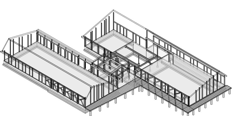
Structures Workshop just completed the structural design of the Hitchcock Center in Amherst, MA meeting the Living Building Challenge. The project (DesignLab Architects) is aiming to be net zero energy, water independent, using all non-toxic materials (all locally sourced wood construction - black spruce gluelam beams, spruce decking, exterior northern cedar frames, eastern white pine, etc). This is one of just a few LBC projects on the East Coast. Below is our Revit model which helped us complete the CDs...
In addition, Structures Workshop (Swansan Builders) was the structural engineer for the first Passive House in Rhode Island. This will lead to energy consumption reduction of 60-80 percent (we designed double wood walls and roof frames for continuous unbroken insulation).

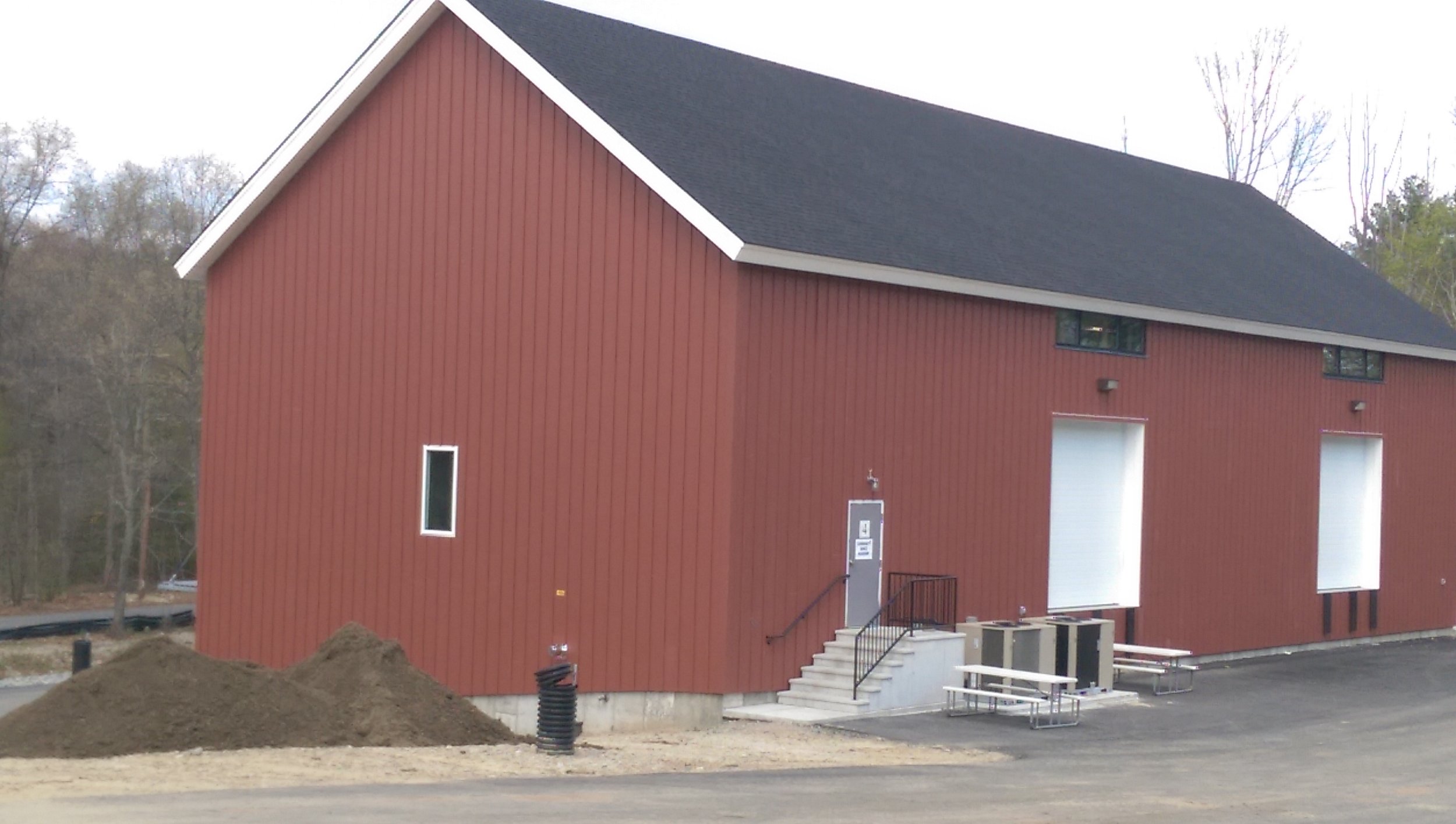
Facilities Building at Walnut Hill almost Complete

We've moved!
Structures Workshop has moved! We purchased a boiler room building in a former knife factory in the Jewelry District of Providence for our new home. This will allow us to grow from 4 to 5 (or 6) as well as provides enough space for a small workshop in the back for testing materials/joints, building stuff, creating steel/wood/glass connections, not sure what. Also, we will finally have our own sink! Come visit us... 18 Imperial Place, Courtyard Building - Providence.
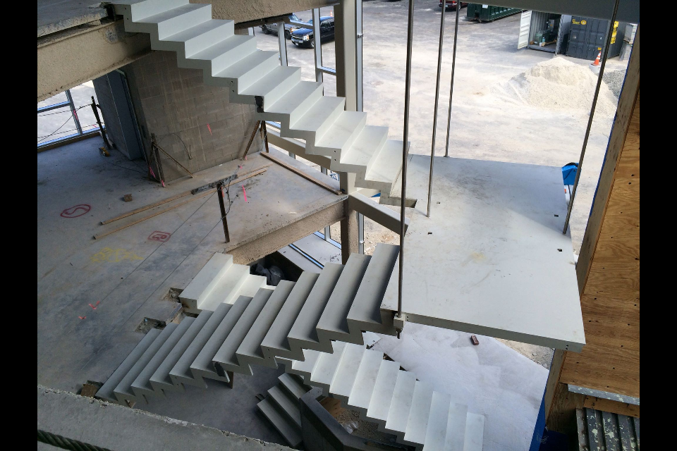
Long Span Stair without Stringers
We designed a long span stair with the appearance of a folded plate. No stringers! (picture below courtesy of Diamond Iron, the fabricator and erector)
The stairs were actually designed with thin saw tooth vertical plates hidden within the thickness, here is an FEM screen shot...
 The stair was not governed by strength (only about 11ksi) but by live load deflection (1/4") and vibration. We wanted to keep the vertical frequency above about 8Hz without adding to the steel weight. This was set to limit affect of exciting the second harmonic when descending stairs quickly. We did this by trimming down the thickness of the tread and risers, and increasing the fin plates thickness. Also, we reduced the landing hangers from 6 to 4 and cantilevered the corners of the 3" platform over 4 ft.
Philosophy of Engineering: What It Is and Why It Matters
Published "Philosophy of Engineering What It Is and Why It Matters" in the Journal of Professional Issues in Engineering Education and Practice...  http://ascelibrary.org/doi/abs/10.1061/(ASCE)EI.1943-5541.0000205
Here is an early DRAFT.... (with permission from ASCE)
http://ascelibrary.org/doi/abs/10.1061/(ASCE)EI.1943-5541.0000205
Here is an early DRAFT.... (with permission from ASCE)
Hanging Wood Sculpture Almost Complete at UMass Lowell
We were the engineers for this huge wood sculpture called "the latern", hanging within a large atrium space at UMass Lowell. We collaborated with the Architects who created the lantern, Perkins+Will, and visited the project this week. It is nearing completion... 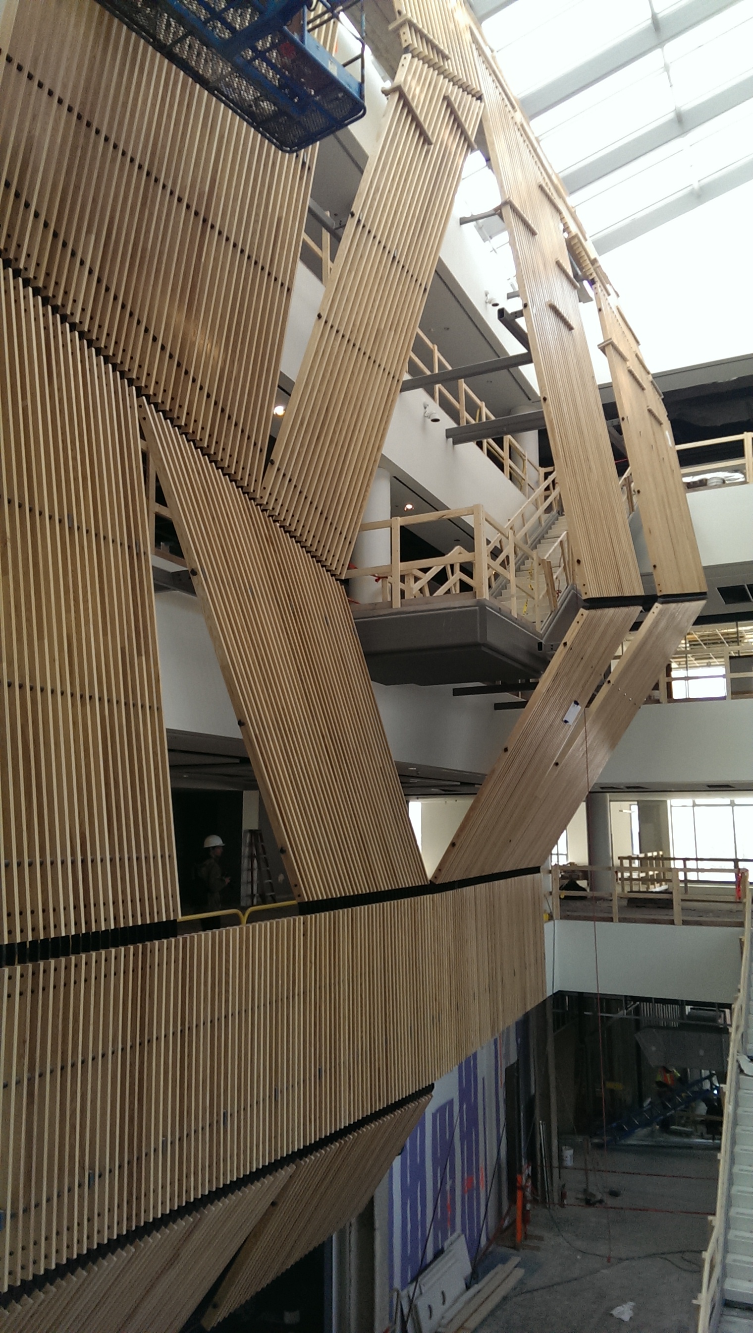
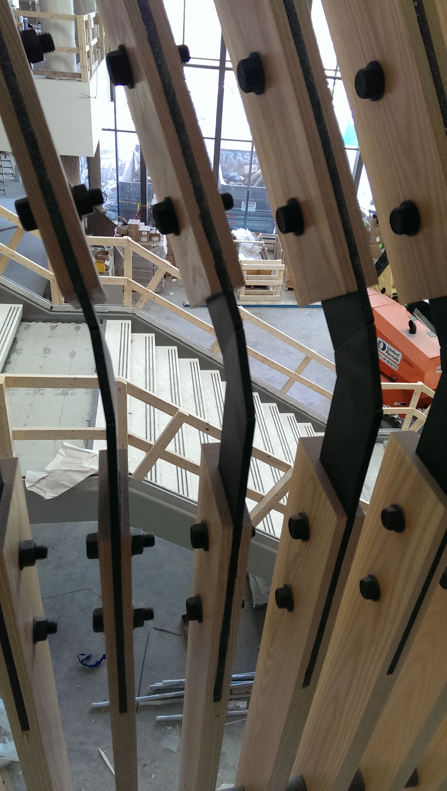
 We designed the two feature staircases as well in this space, and the wood wall hangs and folds around them.
Infinite Load Path Created in Steel House
I while ago, my friend and I wrote about the analytical challenge of a peculiar type of framing orientation that we called the Infinite Load Path, which can occur in projects - but we didn't have a built example at the time. Now we do. It looks something like this in plan, and can occur around openings (not a great example, but illustrative)...

There are two associated problems with this framing layout, one of analysis and the other of construction. To erect this framing layout would require temporary shoring of at least one of the inside corner connections. In practice, therefore, we should make every attempt in avoiding this condition, although the completed system is perfectly stable (and is easily solved by most structural analysis programs). Recently, we designed one on a project. It required the edge of two finished openings to be lined up (so we could not do a continuous beam).
 You can see the built steel framing below, the two arrows indicate two separate but parallel beams...

We know this system is stable from statics, but it seems to have a dynamic or iterative quality (point loads seems to move in circles). If we think about a uniform load applied to all four beams, how do we solve for equilibrium? And second, how and when does the system actually reach equilibrium? See that article for suggestions.
“Infinite Load Path” beam systems can be shown to work for larger scale structures too. We built a small dome at RISD a few years back that could be scaled much larger...
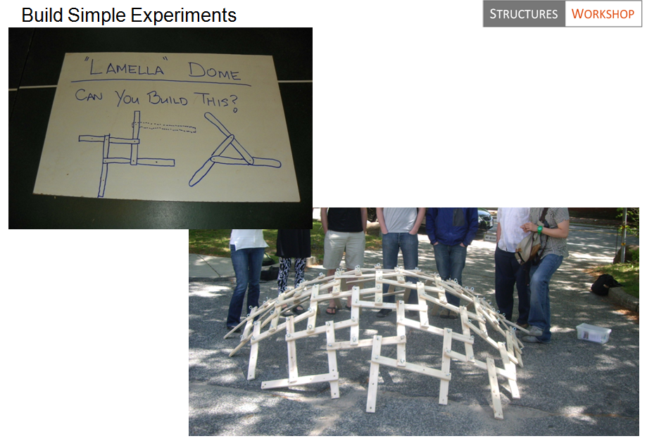
They can become domes only because if stacked they form curvature based on the tangent of the thickness of the material to the length. But they can be flat as well. Lamellas (and tensegrities, for that matter) are special cases of these types of framed structures (where member sizes is repeated, or Platonic/Archimedes solids used as starting points for geometry).
For this steel project, it was economical and efficient (even though erector had to shore the first member to build the next three). But again, these types of structures should only be used when simpler framing is not possible. Here is the house during final days of construction...


Truth (and Beauty) are Useless, Seek "Good" instead
Beauty, Truth, or Goodness? In a previous article I wrote called 'Twilight of the Idols', we learned (from Nietzsche) that truth is not a useful concept to designers and structural engineers. Let science (or religion, for that matter), have ownership of truth. We can do 'truth' in our spare time. We also have learned (from manifesto on goals being useless), that beauty is a by-product of our work, not something we need to consciously drive towards. What is left? Goodness. Quality. We should focus in this arena of Plato's Trinity, not the other two.

We design buildings, bridges and other structures, but how do we do this well or how do we improve over time? Does our conception of the structure to be built change with experience and improve? Yes, we learn what is feasible and what is practical with experience but what about Quality? When we develop options for consideration or make a decision based on a certain amount of information, how do we choose the best option and make the best decision?
The entries in the Manifesto blog herein, are some attempts at improving design, and many others have written on the subject for structural engineers. For example, David Billington in The Tower and the Bridge, described how the best designers of the past made engineering decisions based on a balance of efficiency, economy and elegance. We can add to those considerations such as durability, constructability along with resilience and sustainability. Also, when thinking about quality, we can do this in two ways, the end (the structure itself), and the process (the design process). We can say to ourselves “I want quality in the form of the structure and the assemblage of materials” or “I want to design well, I want to be good at engineering decision making”. These may overlap. For example, how does the description or idea of the final artifact as “quality”, create a path for working towards it? After all, we are typically designing new and novel things (i.e.. not pancakes that we can taste, recook and/or adjust ingredients easily).

In may be worth investigating what the Philosophers of antiquity thought on the subject of quality, beauty, and art. I found that a terrific anthology to get a good background on this subject is Hofstadter’s Philosophies of Art and Beauty: Selected Readings in Aesthetics from Plato to Heidegger. In it we find the beginnings of our conception of quality. For example, we find that Aristotle, in his Parts of Animals Book I believes that one has to have a clear picture of the structure first (the end), and simply work towards that.
He starts by forming for himself a definite picture, in the one case perceptible to the mind, in the other sense of his end – the builder of a house – and this he holds forward as the reason and explanation of each subsequent step he takes. Art indeed consists in the conception of the result to be produced before its realization in material... The plan of the house has this or that form; and because it has this or that form, the construction is carried out in this or that manner. For the process of evolution is for the sake of the thing finally evolved, and not this for the sake of the process. (Aristotle, Parts of Animals Book I, 640).
But how does one conceive of an end first? How does one know ahead of time that something will be good, correct and well proportioned or efficient and economical? Here we learn from Aristotle, that good design is done by those who can take a complex task and split it up into smaller and simpler problems. One step at a time. Engineers are pretty skilled at this. It may also be that when a good engineer has a vision, or an end to be aimed at, he/she has a command of measure (what we now may think of as proportion). The engineer, according to Plato, must know the nature of measure for the proper portioning of structures (artistic as well as scientific). Measure for Plato, is essential to quality and is the fundamental principle that defines quality. A column should be this size, not that, for many reasons.
Basic to any art, is the art of measure without which there can be no art at all. For to know the proper size of a column, proportion of a window, the proper organization of language in a poem, is to command the art of measurement.... There are accomplished men, Socrates, who say…the art of measurement is universal, and has to do with all things.” (Plato, Statesman 285b)
So if we think we succeeded in the proper form by creating something well proportioned, how do we know we are right? How do we judge quality?
Every art does its work well – by looking to the intermediate and judging its work by this standard. (Aristotle, Nicomachean Ethics Book II 1106)
He agrees that the science may have a hand in the judgment of art.
The chief forms of beauty are order and symmetry and definiteness, which the mathematical sciences demonstrate in a special degree. (Aristotle, Metaphysics Book XIII 1078)
So we can learn a bit about what Aristotle and Plato thought about how to conceive and judge quality structures, but we have learned less about the individual engineering designer. It is the engineer's personal ability that contributes to great work. The engineer that seeks personal excellence will see that transcend themselves and into the built world. It may be obvious that all designers aim for quality structures as Aristotle suggests in his opening to Nicomachean Ethics.
Every art and every inquiry, and similarly every action and pursuit, is thought to aim at some good; and for this reason the good has rightly been declared to be that which all things aim. (Aristotle, Nicomachean Ethics Book I 1094).
And to which all engineers should aim - but not aim towards goodness, it is not a goal, it is a way. Here we are back to the process of design, how the individual designer takes action and aims at some good, or quality (and being good is integral to this, but not going there). It a process that requires constant reflection and the way to create safe, economical and efficient structures and do it better and better over time.
We know that the design of structures combines the objective science (material mechanics) with more complex subjective decision making requiring sound judgment (heuristics). Problems encountered by the structural engineer are complex and nuanced and require experience and judgment to better sift through the multiple design ideas. If you have been reading this blog, one recurring theme is that idea that engineering is more of an art than a science. Not art as beauty or aesthetic vision, not at all. Again, that is useless. In the forward to Nervi’s book Structures, Mario Salvadori says it best when describing one of the greatest structural engineers of the 20th century:
Nervi’s results are not achieved by consciously trying to meet aesthetic demands, but by tackling the fundamental structural problems from the outset, and giving them an obvious and clearly articulated solution. Beauty, says Nervi, is an unavoidable by-product of this search for satisfactory structural solutions. [Salvadori 1956: vi]

So no answers or short cuts to quality, just more questions. The original of my poem on Nervi called "The Structure That Sings" (later published in STRUCTURE) has a similar conclusion (beauty as an end and not sought after)...

There is something called "design science" (bio-mimicry, form finding, geodesic geometry, etc) which has mathematical, scientific, and objective procedures to create form. So "truth in form" is okay - but again, it is very rare that good design is driven by scientific methods. It can be, but more often not. So, if I could re-write this, I would replace "truth in form as a means", with "quality as the means". Quality, is by definition, process. As Pirsig would say, quality is "the knife edge of experience", and living in it and with it, beauty just becomes.
2013 - Another Record Year for SW
2013 was a terrific year with a new record 149 projects along with 20 new and great clients! This allowed us to reinvest in new technology including 3 new and powerful computers, 6 large monitors, new/updated licenses of Revit, SAP, ETABs, SAFE, Tedds, and BlueBeam. We continue to have amongst the best computer/software infrastructure in the industry, as much as the largest firms, to tackle all types of projects. In addition, we have hired our 4th engineer at the beginning of 2014 (see previous blog entry). Check back with blog/website for completed 2013 projects which have not been included yet. More to come!
Lincoln Center Theater
Just stumbled upon some great pictures of our Lincoln Center project. We were the erection engineers for this long span roof truss....
![lct3-progress3[1]](http://static1.squarespace.com/static/5b50dee412b13f916dbf6993/5b64a7fce0c9380bf64954f1/5b64a805e0c9380bf64956d0/1533323269487/lct3-progress31.jpg?format=original)
This included determining each pick, how to hang entire truss on existing wall, reinforcing of existing roof for construction loads, reinforcing existing retaining wall for the crane loads, rigging, full construction sequencing etc.
![LCT_3[1]](http://static1.squarespace.com/static/5b50dee412b13f916dbf6993/5b64a7fce0c9380bf64954f1/5b64a805e0c9380bf64956da/1533323269671/LCT_31.jpg?format=original)
Here is one portion of our 30+ drawings...

Final Building (Long Span Truss above building)...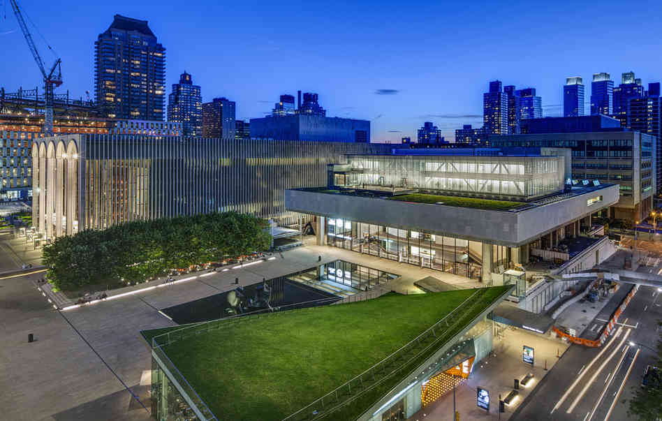
In the foreground you can see the green roof that is hyperbolic. We were also involved in that project (Arup was EOR) back in 2009. We designed all the connections for that roof.
An Inquiry into Quality - Nelson to Speak at SEAofNC
On Sept 27, 2013, Erik Nelson will be speaking at the Structural Engineers Association of North Carolina annual conferance. For more info... http://www.seaofnc.org/Portals/22/Conference%20brochure.pdf
Block Island House
Here is are two picuctures of a house we designed in Block Island (pics from Design Builder - Engine House)...
![tumblr_mofnd7lfBa1r2n6jqo4_1280[1]](http://static1.squarespace.com/static/5b50dee412b13f916dbf6993/5b64a7fce0c9380bf64954f1/5b64a805e0c9380bf64956c9/1533323269377/tumblr_mofnd7lfBa1r2n6jqo4_12801.jpg?format=original)
![tumblr_mp5z356ypx1r2n6jqo1_1280[1]](http://static1.squarespace.com/static/5b50dee412b13f916dbf6993/5b64a7fce0c9380bf64954f1/5b64a805e0c9380bf64956cb/1533323269414/tumblr_mp5z356ypx1r2n6jqo1_12801.jpg?format=original)
IRC 2012 / IBC 2012 / ASCE 7 10 - Why did wind speed increase 30mph?
One big change from IBC 2009 / ASCE 7 05 is that wind speeds in IBC 2012 / ASCE 7 10 are now "ultimate" values and associated with risk category and have increased about 30%. For example, in the typical risk cat II, wind speed in Providence is now 133 mph (instead of 100 mph before). That increase is counter balanced by new load combinations that reduce the wind load factor within the ASCE 7 USD/LRFD combos from 1.6 to 1.0 (or from 0.8 to 0.5) depending on the combination used. Since wind pressure is proportional to velocity squared, it turns out that in Providence, wind pressure did increase a little overall, since wind speed increased 133mph^2/100mph^2 = 1.77, but the load factor in the ASCE 7 10 combos only went down from 1.6 to 1 (so wind pressure after doing the load combinations did still increase about 10% or 1.77/1.6 in Providence). It also depends a little on type of load combinations. For Boston, the wind in Cat II went from 105mph to 128mph, and 128mph^2/105mph^2 = 1.49 which is less than 1.6. So for Boston wind pressure went down about 8% +/-, but in Providence it went up about 10% +/-. Not a big deal but here is the problem... Believe it or not, our brilliant code writers are using different wind speeds now for the IRC and IBC codes. The IBC has gone to an ultimate strength value to be used (LRFD) while the IRC has the old 3-sec gust data (based on ASD). So it is Vult for IBC and Vasd for IRC - but both use ASCE-7 2010 as the reference standard. Per IBC 2012 section 1609.3.1 you can get back to ASD values by multiplying the ult values by the square root of 0.6 (or 0.775). So, for Providence 133mph x 0.775 = 103 approx= 100mph which is what can be used in IRC/SBC-2 (this conversion is also necessary when comparing to others standards/triggers that are not updated).
Yes, this is going to lead to much confusion because load cases are now mixed up with load combinations. Here is another problem - if I have a house and I choose to use the IRC/SBC-2 wind speeds (say 100mph based on Vasd), I better not use the ASCE-7 10 combinations - that is double dipping since there is already a 0.6W factor within the new ASD combos (instead of 1.0W). So if you are using IRC wind speeds, you should use the old ASCE 7 05 load combinations - but that is no longer a reference standard! Therefore, one option is if you are using IRC wind speeds, you can factor them up by 1/0.775 to get pressures, and then use the ASCE-7 2010 combinations. What a mess! I am planning on using Vult from ASCE 7 10 for both IBC and IRC for wind to avoid load combo confusion.
These code people are obviously not designers because this new code will lead to more confusion and more errors (and how would a building official understand this? they don't see combos used, only mph on drawings). It was already unnecessary to go to Vult in my opinion, but then for IRC to not follow IBC is really strange. Good luck with this! My understanding is we are in a transition, and IRC will eventually adopt the same methods as IBC.
Single Plate Shear Connections with New Eccentricity
The following post contains several ideas that will form a future article in a magazine (by Erik Nelson and Doug Seymour), therefore comments are welcome! ... In the 13th Edition AISC Steel Construction Manual, eccentricity was neglected for most conventional single-plate connections (shear tabs). Some of this practice was based upon the 20% reduction in bolt strength for end loading (a condition that doesn’t apply to shear connections). As a result, the 14th Edition AISC Manual contains recommendations for accounting of the eccentricity in conventional single-plate connections. Now bolt shear calculations must include an eccentricity (typically half of the distance from the bolt line to the weld line). This is an important change, since the reduction in bolt shear (and possibly bolt bearing strength) can be significant even for small eccentricities.
Consider the conventional single-plate connection with SSL holes illustrated in Figure 1.

The ICR method is used to account for the effect of the eccentric load on the bolt shear strength. For a number of common connection types and eccentricities, including the configuration of the conventional single-plate connection, the effective number of bolts for that connection, C, is given in the AISC Manual in Tables 7-6 to 7-13. The values published in AISC Manual Table 7-6 are useful, but the small eccentricities common in single-plate connections often fall below the entries in the table.
Since many conventional single-plate connections have a = 2 in. or 2½ in. (and a/2 values of 1 in. or 1¼ in.), we have prepared C values for these eccentricities for the convenience. The data is given in Table 2 with the additional information beyond that given already in Table 7-6 shown shaded.

The C values given in AISC Manual Tables 7-6 to 7-13 are determined using the strength predicted for each bolt group by that method, divided by the strength of one bolt under concentric load. The result is an equivalent number of bolts for the given bolt pattern, with the given load eccentricity, to be used in calculations.
In addition to bolt shear, this same C/N approach can be used to account for the effect of eccentricity on the nominal bolt bearing strength. Using C and N, the total number of bolts in the connection:
Rn,bolt = (C/N) 2.4dtFu
The strength of the connection can be determined as the sum of the individual bolt bearing strengths. For simple shear tabs with one line of bolts, eccentricity can still be ignored in bearing calculations according to the manual. In fact, letting the bolts deform the material in bearing has the advantage of increasing the flexibility of the connection to reduce moment transfer. This has bean confirmed by tests for single lines of bolts with small eccentricity. For extended plates, the C/N method can apply and is simple to perform by hand calculations since C has already been determined for bolt shear.
You may notice that we left out the tearout portion of the bearing equation. Unfortunately, we do not have a simple method of accounting for tearout in eccentrically loaded bolt groups of shear connections. In typical configurations of a single column of bolts, only one bolt may experience tearout, but it is not clear how to satisfy statics under eccentricity (horizontal components must sum to zero) when for example, the lower bolt experiences tearout and the upper bolt experiences bearing. We recommend sizing the plate such that the edges distances are large enough so tearout does not control for extended plate shear connections. There are likely more advanced methods to account for tearout, but any method must satisfy statics and equilibrium, in addition to having a design with sufficient ductility to redistribute the loads.