Technical Tid Bits

Erik to Present at “Steel School”

Steel School: Practical Wisdom from 3 Industry Experts

3.0 SEAMASS-Certified PDHs

On October 9, SEAMass is hosting Steel School, an informative three-part seminar that will cover several aspects of designing with and working with steel.

Braced Frames, Moment Frames and Cantilevers
Presenter: Erik Nelson | Structures Workshop

• Lateral systems, axial thru forces, collector forces with amplification, and R factors
• Simple design advice on when axial forces are too high for beam web connections and when moment designation should be used
• Load paths on axial thru forces and moments on stiffener welds within the column web.
• Stiffeners and doubler plates within moment frames, a discussion
• Larges difference in connection review and design of cantilevers vs lateral moment connections– what to look out for

Concrete in Torsion

Please join SEARI for an educational presentation on torsion in concrete by Erik Nelson, PE, SE of Structures Workshop, Inc. Erik will introduce the basics of designing for torsion using ACI 318-11.  He will describe best practices for evaluating various components of concrete structures for torsion, including stiffness assumptions in modeling spandrel beams.  Please note that the event will take place at the Department of Administration, One Capitol Hill, Providence in Conference Room B on Tuesday, May 20, 2014.

Infinite Load Path Created in Steel House

I while ago, my friend and I wrote about the analytical challenge of a peculiar type of framing orientation that we called the Infinite Load Path, which can occur in projects - but we didn't have a built example at the time.  Now we do.  It looks something like this in plan, and can occur around openings (not a great example, but illustrative)... 1 ilp

There are two associated problems with this framing layout, one of analysis and the other of construction.  To erect this framing layout would require temporary shoring of at least one of the inside corner connections.  In practice, therefore, we should make every attempt in avoiding this condition, although the completed system is perfectly stable (and is easily solved by most structural analysis programs).   Recently, we designed one on a project.   It required the edge of two finished openings to be lined up (so we could not do a continuous beam).

2 ilpYou can see the built steel framing below, the two arrows indicate two separate but parallel beams...

3 ilp

We know this system is stable from statics, but it seems to have a dynamic or iterative quality (point loads seems to move in circles).  If we think about a uniform load applied to all four beams, how do we solve for equilibrium?  And second, how and when does the system actually reach equilibrium?  See that article for suggestions.

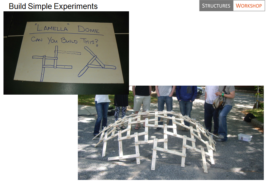
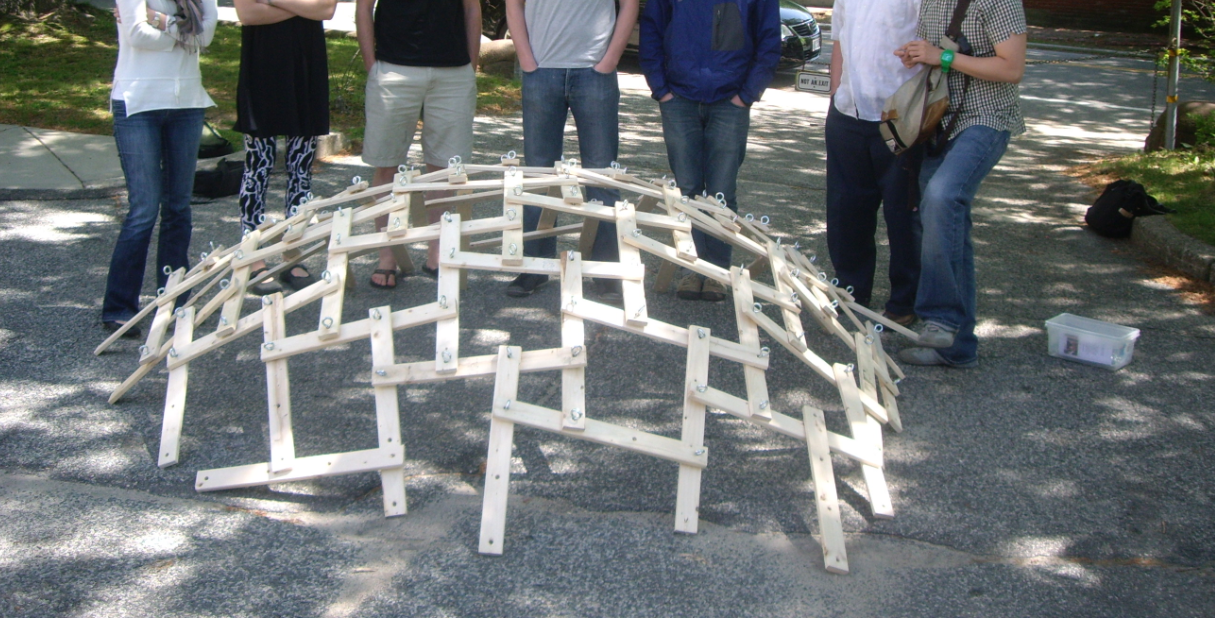
“Infinite Load Path” beam systems can be shown to work for larger scale structures too.   We built a small dome at RISD a few years back that could be scaled much larger...

4 ilp

They can become domes only because if stacked they form curvature based on the tangent of the thickness of the material to the length.  But they can be flat as well.   Lamellas (and tensegrities, for that matter) are special cases of these types of framed structures (where member sizes is repeated, or Platonic/Archimedes solids used as starting points for geometry).

For this steel project, it was economical and efficient (even though erector had to shore the first member to build the next three).   But again, these types of structures should only be used when simpler framing is not possible.  Here is the house during final days of construction...

IMG_0168IMG_0171

IMG_0207

IRC 2012 / IBC 2012 / ASCE 7 10 - Why did wind speed increase 30mph?

One big change from IBC 2009 / ASCE 7 05 is that wind speeds in IBC 2012 / ASCE 7 10 are now "ultimate" values and associated with risk category and have increased about 30%.  For example, in the typical risk cat II, wind speed in Providence is now 133 mph (instead of 100 mph before).  That increase is counter balanced by new load combinations that reduce the wind load factor within the ASCE 7 USD/LRFD combos from 1.6 to 1.0 (or from 0.8 to 0.5) depending on the combination used.   Since wind pressure is proportional to velocity squared, it turns out that in Providence, wind pressure did increase a little overall, since wind speed increased 133mph^2/100mph^2 = 1.77, but the load factor in the ASCE 7 10 combos only went down from 1.6 to 1 (so wind pressure after doing the load combinations did still increase about 10% or 1.77/1.6 in Providence).   It also depends a little on type of load combinations.  For Boston, the wind in Cat II went from 105mph to 128mph, and 128mph^2/105mph^2 = 1.49 which is less than 1.6.   So for Boston wind pressure went down about 8% +/-, but in Providence it went up about 10% +/-.  Not a big deal but here is the problem... Believe it or not, our brilliant code writers are using different wind speeds now for the IRC and IBC codes.    The IBC has gone to an ultimate strength value to be used (LRFD) while the IRC has the old 3-sec gust data (based on ASD).   So it is Vult for IBC and Vasd for IRC - but both use ASCE-7 2010 as the reference standard.     Per IBC 2012 section 1609.3.1 you can get back to ASD values by multiplying the ult values by the square root of 0.6 (or 0.775). So, for Providence 133mph x 0.775 = 103 approx= 100mph which is what can be used in IRC/SBC-2 (this conversion is also necessary when comparing to others standards/triggers that are not updated).

Yes, this is going to lead to much confusion because load cases are now mixed up with load combinations.  Here is another problem - if I have a house and I choose to use the IRC/SBC-2 wind speeds (say 100mph based on Vasd), I better not use the ASCE-7 10 combinations - that is double dipping since there is already a 0.6W factor within the new ASD combos (instead of 1.0W).   So if you are using IRC wind speeds, you should use the old ASCE 7 05 load combinations - but that is no longer a reference standard!   Therefore, one option is if you are using IRC wind speeds, you can factor them up by 1/0.775 to get pressures, and then use the ASCE-7 2010 combinations.   What a mess!   I am planning on using Vult from ASCE 7 10 for both IBC and IRC for wind to avoid load combo confusion.

These code people are obviously not designers because this new code will lead to more confusion and more errors (and how would a building official understand this?  they don't see combos used,  only mph on drawings).   It was already unnecessary to go to Vult in my opinion, but then for IRC to not follow IBC is really strange.   Good luck with this!   My understanding is we are in a transition, and IRC will eventually adopt the same methods as IBC.

Single Plate Shear Connections with New Eccentricity

The following post contains several ideas that will form a future article in a magazine (by Erik Nelson and Doug Seymour),  therefore comments are welcome! ... In the 13th Edition AISC Steel Construction Manual, eccentricity was neglected for most conventional single-plate connections (shear tabs). Some of this practice was based upon the 20% reduction in bolt strength for end loading (a condition that doesn’t apply to shear connections).  As a result, the 14th Edition AISC Manual contains recommendations for accounting of the eccentricity in conventional single-plate connections. Now bolt shear calculations must include an eccentricity (typically half of the distance from the bolt line to the weld line).  This is an important change, since the reduction in bolt shear (and possibly bolt bearing strength) can be significant even for small eccentricities.

Consider the conventional single-plate connection with SSL holes illustrated in Figure 1.

1

The ICR method is used to account for the effect of the eccentric load on the bolt shear strength. For a number of common connection types and eccentricities, including the configuration of the conventional single-plate connection, the effective number of bolts for that connection, C, is given in the AISC Manual in Tables 7-6 to 7-13. The values published in AISC Manual Table 7-6 are useful, but the small eccentricities common in single-plate connections often fall below the entries in the table.

Since many conventional single-plate connections have a = 2 in. or 2½ in. (and a/2 values of 1 in. or 1¼ in.), we have prepared C values for these eccentricities for the convenience. The data is given in Table 2 with the additional information beyond that given already in Table 7-6 shown shaded.

2

The C values given in AISC Manual Tables 7-6 to 7-13 are determined using the strength predicted for each bolt group by that method, divided by the strength of one bolt under concentric load. The result is an equivalent number of bolts for the given bolt pattern, with the given load eccentricity, to be used in calculations.

In addition to bolt shear, this same C/N approach can be used to account for the effect of eccentricity on the nominal bolt bearing strength. Using C and N, the total number of bolts in the connection:

Rn,bolt = (C/N)  2.4dtFu                                                                            

The strength of the connection can be determined as the sum of the individual bolt bearing strengths.   For simple shear tabs with one line of bolts, eccentricity can still be ignored in bearing calculations according to the manual.  In fact, letting the bolts deform the material in bearing has the advantage of increasing the flexibility of the connection to reduce moment transfer.  This has bean confirmed by tests for single lines of bolts with small eccentricity.  For extended plates, the C/N method can apply and is simple to perform by hand calculations since C has already been determined for bolt shear.

You may notice that we left out the tearout portion of the bearing equation.  Unfortunately, we do not have a simple method of accounting for tearout in eccentrically loaded bolt groups of shear connections. In typical configurations of a single column of bolts, only one bolt may experience tearout, but it is not clear how to satisfy statics under eccentricity (horizontal components must sum to zero) when for example, the lower bolt experiences tearout and the upper bolt experiences bearing.  We recommend sizing the plate such that the edges distances are large enough so tearout does not control for extended plate shear connections.  There are likely more advanced methods to account for tearout, but any method must satisfy statics and equilibrium,  in addition to having a design with sufficient ductility to redistribute the loads.

"Economical Welds" published in MSC

In January 2013, Ethan and I published an article in MSC related to reducing the amount of expensive CJP welds and substituting fillets welds instead.   We provided a simple table to assist the engineer and fabricator in using fillets instead of CJP welds...

See the following PDF for more info: Economical Steel Design (MSC)

The Secret to Trusses

Trusses are simply built out of triangles - and they are actually defined as such.  Some member will be in tension and some members will be in compression (about half).  The trick, and at times difficulty, is to determine which members are in tension and which members are in compression.   We can simplify things by recognizing there are only two types of triangles in trusses.  One that has two tension members, and one has only one tensions member (tension = rope, compression = wood in below image)...

If I extend this into a longer truss and simply replace the compression member with the tension member, we have...

Do you see the two types of triangle?  Also as you can see, the bottom chord is in tension and the top chord is in compression.   The trick to determining which diagonal or vertical member is in tension or compression, is ask if they follow the same curve as a hanging chain would between the two end points.  If they do, they are in tension, if not, they are in compression.HANGING

This is a stable truss for gravity loads...

What is really interesting about changing out the sticks for strings when they are in tension, is the fact that the entire truss can now be folded!   Check it out...

Think about how this can be extend to designing and building folding architecture, temporary construction, or tents etc.

Build a Lamella Dome

Lamella structures are created using many pieces of the exact same member shape and connection.   So 1000 pieces of something and stacked in a certain manner...

You can imagine it can get pretty big depending on the size of the individual beams and the quantity.   Here a pic with my RISD class a few years back that we built together from sticks I cut in my basement and eye hooks to temporarily hold the pieces together...

I wrote about the physics of this system as well... Published Infinite Load Path?” October 2007 Structure Magazine if interested.

The Perfect Arch

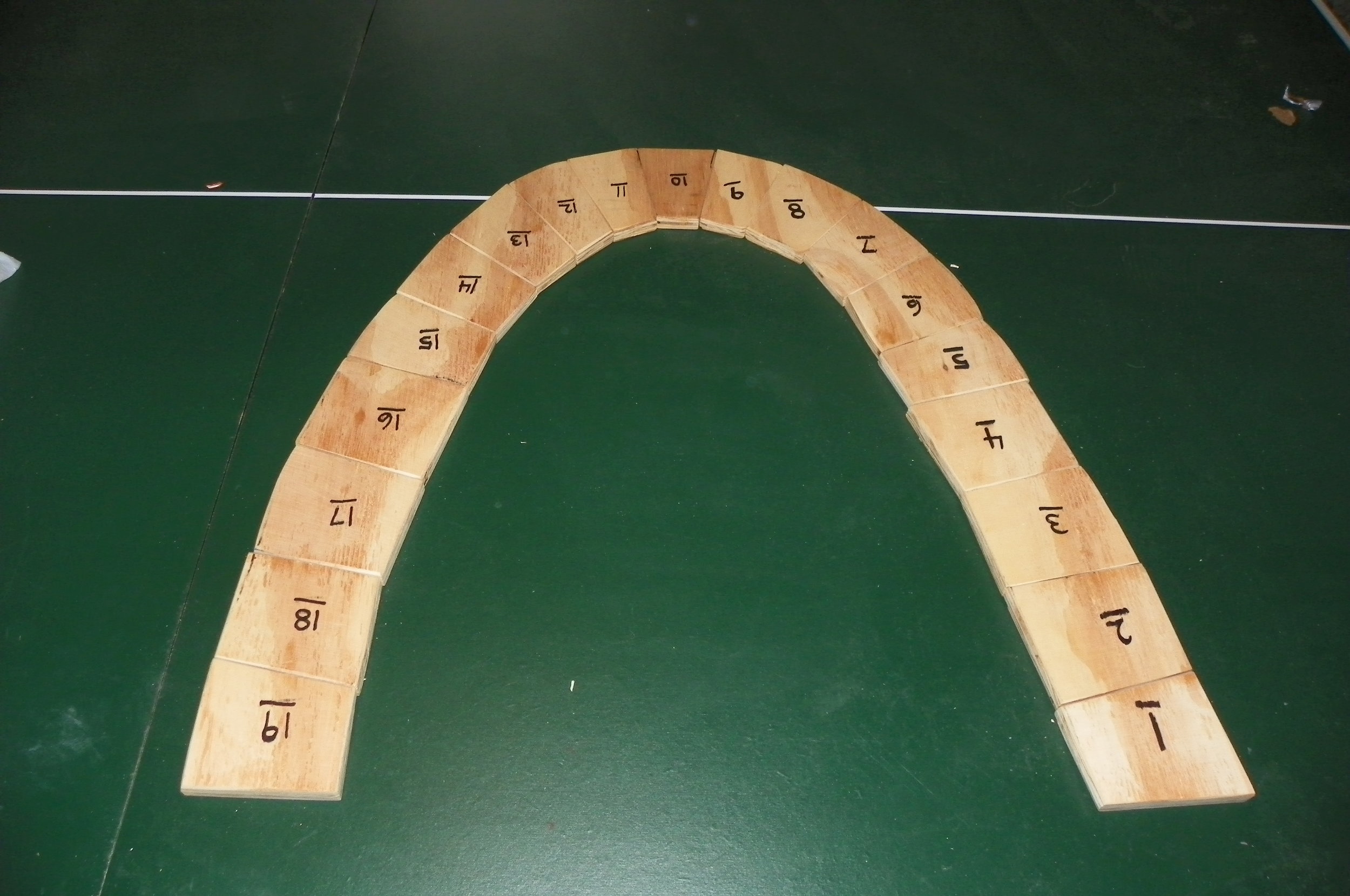
For a arch to be prefect, it must be shaped such that it is in uniform compression.   Basically the inverse of a hanging chain.   So we can build what Robert Hooke describes in 1675 "as hangs the flexible line, so but inverted will stand the rigid arch".  So, we can hang strings from a sheet of plywood, trace and cut... As the thin shell innovator Heinz Isler would say "One does not actually create the form; one lets it become, as it has to according to its own law".  Also, this is an exceedingly complex mathematical shape called the hyperbolic cosine or catenary.

So we cut ...

Remove...

And build...

EOR and Shear Connection Design of Steel Buildings

This blog entry addresses engineering, detailing, and erection of shear connections which represent 95% of the connections on every steel project. While they are often unfairly regarded as simple, they are rarely simple. Shear connections are complex due to the many different types of connections, number of limit states to check, as well as geometry and erection complexity. I will compare and rate the various methods the Engineer of Record (EOR) uses to provide shear demands. In addition, common types of shear connections will be presented and discussed. Shear connections are rarely controlled simply by the number and capacity of the bolts, and this paper will examine all limit states and discuss what to look out for during shop drawing review. There has been an ongoing debate as to the responsibility for the design of steel connections for building projects. As a result, different practices are used in design office varying across the country. For instance, on the west coast, the connections are often fully designed by be EOR as part of the construction documentations. Whereas, on the East coast, the connection design criteria and requirements are specified on the construction documents, but the final design is delegated to a licensed professional engineer (often hired by the fabricator) in the state of jurisdiction. I have the rather unique experience of seeing both sides of the issue of connections design, first as an EOR designing buildings, specifying connection criteria and checking the shop drawings for conformance. And now for the past four years, I have worked for fabricators to design connections based on the requirements specified by the EOR. It through seeing this issue from both sides, that I have an appreciation for the importance of the proper attention to shear connection design.

The 2010 edition of the AISC Code of Standard Practice outlines three options for the responsibility of the connection design. It presents a new (albeit already established and widely used) third option where by the EOR delegates the connection design to a professional engineer hired by the fabricator. This article is not a review of these options, but rather a presentation of the various practices used by the EOR to specify the shear connection requirements as seen by the author in review of hundreds of Construction Documents. It is the hope that it becomes clear that this new third option should become the industry standard for all connections including simple shear connections.

Why Every Shear Connection Must be Checked

Most often, at least on the East Coast, the steel connection design is relegated to the fabricator and the EOR provides demand criteria and typical details for the design of the connections. The fabricator either has an in house engineer or hires a connection engineer to design the connections (typically the shear, moment and bracing connections). .

However, in some cases the EOR does not always require the shear connections to be designed by an engineer, only the moment and bracing connections. This is a mistake. While shear connections are perceived as simple, they often are not. Take for instance the most common type of shear connection - the beam-to-beam connection, which is actually pretty complicated. As is commonly known, all beam-to-beam shear connections have a top cope, which can make the design tricky. In addition, the cope varies based on the size of the girder – so it is not uncommon for the same size beams with the same type of connection material (shear tabs, bolts, etc) will have very different capacities. For example, a W12x14 framing into a W16x31 has a very different capacity than a W12x14 framing into a W12x53 even if the shear connection is identical, see Figure 1.
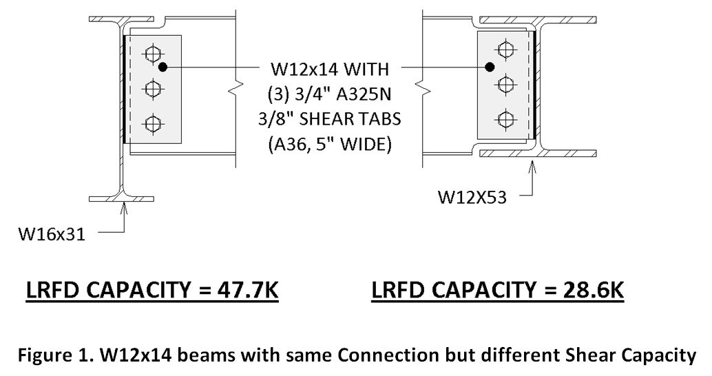
Not only is the W12x14 double coped when framed into the W12x53, but the copes are larger (both deeper and wider due to the thicker and wider girder flange) in comparison with the W12x14 framing into the W16x31. The reduced section due to the large copes significantly decreases the shear capacity of the connection by nearly half. Often times shear connections are not controlled by the bolt shear capacity (especially light beams with double angle shear connections). They may be controlled by bolt bearing, shear rupture of the web, block shear capacity of the web or coped section capacity. In the following sections we will explore the various ways the engineer of record specifies shear demands in addition to clarifying the different shear connection types.

EOR Methods of Providing Demands

There are a variety of methods that are used by engineers to provide the fabricator the shear demands for the design of shear connections, and based the author's experience, some are good and some should be avoided.

Method 1: Provide Actual Shears on Each Beam on the Plans

This method is when the EOR provides the actual shear on the plans for every beam. This provides a uniform reliability in all of the members and the most accurate and efficient connections result.


Method 2: Provide a Table of Shear Values

This is method can work but it may be overly conservative for some beams on the project if done improperly. The table on the left is too simplistic and greatly overestimates the shear demand on lighter sections. For example, a W18x35 will have the same demand as a W18x76. The author derived the right table based on the plastic modulus of the beam and studied each connection type and number of bolts required. The right table is a good one and feels free to use it on your project if appropriate. You can select the ASD or LRFD method, it really doesn’t matter.


Method 3: Shear demands based on Length of Beam

This is a very common method. It is provided in many different forms on the general notes but it is always based on the maximum total uniform load tables in the AISC manual. These tables are based on the moment capacity of the beam in which the max uniform load is “backed out” and the shear is determined. So these tables are based on the following: M=wL2/8 and since V=wL/2, then M=VL/4 or V=M/(L/4). Paradoxically, the longer the beam - the smaller the shear demands. Therefore, beams will have to be designed close to their flexural capacity for a connection to be reasonable. Figure 2 clearly describes the absurdity of this method. The shorter member requires much larger bolts and tabs, in addition to the welded doubler plate to meet the demand.

For composite beams, the EOR will add a multiplier of anywhere between 1.5 and 2.3 on top of this shear to account for the increased moment capacity due to composite action with the concrete slab. For cantilevers, the EOR should be careful because this method is inappropriate, since the maximum total uniform load tables are based on simple span and cantilevers are usually not governed by strength.

For the EOR, this is the simplest method, just a quick note on the drawing. The EOR knows that as long as the beam works in bending (often from their analysis model), the shear connection will work. So the connection is designed for the maximum load it can support. This is often very conservative and inapproiate. It is a very costly method for the owner and fabricator and always leads to larger connections than necessary.

Types and Capacity of Shear Connections

Type 1: Beam to Beam Connections

Generally beam–to-beam connections have at least a top cope. Therefore, the capacities are difficult to calculate (cope section, block shear, etc). These are the most common connection on a project, yet they are often deemed as insignificant and “simple”. This is not the case.

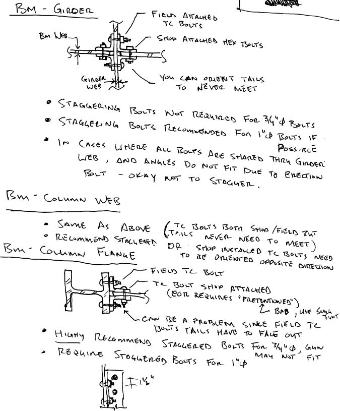
Another complexity is when double angles are required on a project. If all the bolts are shared on each side of the girder web, an erection bolt (or other aid) must be added to the connection to be able to build and meet OSHA requirements. This can lead to problems with fit up and erection sequencing.

The EOR may not realize this, but when requiring the use of double angles for beam-girder connections, it is forcing the detailer to add erection bolts and often to extend the connection angles. In addition, it may affect the erection sequence and force the erector to place the floor beams in a specific sequence. For example, in the case where beams of different depths frame on either side of a girder and share bolts, the deeper beam may have to be erected before the shallower beam on the opposite side of the girder web (so the lower bolts can serve as the erection aid). This can cause delays. A clever detailer will stagger the angles on each side of the same beam web such that either beam can be erected first, but these angles may not fit due to the greater web clearance height required.

An example of inefficient use of connection material is the use of double angles to connect light beams with thin webs. Using 5/16” thick angle legs on each side of a beam web when the web is only a quarter inch is wasteful, yet very common. Furthermore, for beams with weights less than 30plf, it is not the connection angles that control the capacity; it is usually the web in block shear, coped section, or shear rupture (or bolt shear). Therefore, it is the author’s opinion that the EOR should allow the fabricator the freedom to use shear tabs for these reasons. Please note, the bolts in Figure 3 do not need to be staggered for 4” angle legs. If not staggered, this connection will be easier to erect if the shop installs the bolts to the beam web such that the orientation of the tail end of the bolts never meet (spiral pattern in plan).

Type 2: Beam to Column Flange Connections

The simplest connection for an erector to a column flange is a shear tab as shown in Figure 4.

If double angles are used, it may be important to stagger the bolts in this configuration. For the erector to have access to the tails of the column bolts using the TC bolt gun, the tails will always be facing out. This could cause interference with the shop installed bolts on the beam when two tails are on the same side of the beam web. Therefore, the author stronger recommends shear double angle shear connections to column flanges have staggered bolts.

Type 3: Beam to Column Web Connections

Double angles are best for beam-to-column web connections. Erectors that like the use of TC bolts in the field do not like shear tabs since the column flange interferes with the bolt gun.


Key Takeaways for EOR

  • If the EOR is not designing all the shear connections, then require calculations by a PE registered in the state of the project for all connections, including shear connections, to be submitted for approval (similar to all connections). Do not put a table indicating the number of bolts only without checking every limit state of every connection.
  • Try to add shears to the plans (method 1) or provide good table (method 2) – do not use note about the uniform load table method (method 3).
  • Do not require double angles when shear tabs work
  • Let the fabricator and/or fabricator’s engineer select the type of shear connection. Shear tabs are generally preferred for beam-to-beam and beam-to-column flange connections.
  • It is more efficient and cost effective for the fabricator to hire or staff an engineer to design connections specific to their shop and erection standards and practices (e.g. shop bolted, staggered bolts for double angle connections, shop standards for connection material, etc)


Comparison of International Existing Building Code 2012 versus the Rhode Island State Rehabilitation Code

At the request of the Building Code Standards Committee of the RI State Building Code Commission, the Structural Engineers Association of Rhode Island (SEARI) Building Code Subcommittee created this document.  Erik Nelson and Ethan Tirrel of Structures Workshop created this document with the help of David Odeh and other members of SEARI's Building Code Committee.  It compares and contrasts the basic structural provisions of the current Rhode Island State Rehabilitation Code 2002 (“RI SRC-1”) with the 2012 Edition of the International Existing Building Code (“IEBC 2012”).  The IEBC 2012 code will be replacing the SRC-1 code in 2013. Comparison of RI Rehab Code SRC 2002 vs IEBC 2012 Final

The purpose of this document is to provide an overview of the two codes and major changes to building structural design provisions that would occur if Rhode Island chooses to adopt the IEBC 2012 to replace the Rehab Code.

Shipping Container Engineering

A shipping container uses the full depth of the corrugated metal walls to span 40 feet (much like a wide flange beam needs it's web.  It acts as a deep beam which is as deep as the height of the container.  Therefore, structurally, these walls are very important to keep.  To keep costs down, you want to "let the container be a container" and try to keep the walls.  Unfortunately that is often at odds with flexible space and leasing requirements of offices being a minimum of two containers wide.  So some walls need to go.   If the walls are fully or partially removed, the container becomes much more complicated.  It can lose almost all of its stiffness and shear capacity.  You need to introduce reinforcing (horizontal members or columns) because the small base channel cannot span very far in flexure.   You can accommodate small window openings but determining size for unreinforced or minimally reinforced openings can be complicated.  This is due to the walls having different properties in different directions - in the horizontal direction, the web is as flexible as an accordion - but in the vertical and shear orientation it is very stiff.  There is additional complexity in determining how to economically reinforce modified containers - that is, how to minimize field welding and simplify the connections to adjoining containers and foundations.  

The container can be joined the same way they are stacked on a container ship, using steel assemblies that have manual levers to lock the containers together at each of the four corner castings.  They may also need additional welded plates to tie them together horizontally.   Given all the costly reinforcing required, the only way to make a shipping container building economical is very close collaboration with the owner, architect, and builder.  This was the case on the Box Office project.

Coastal Construction in Rhode Island

Rhode Island, all new construction or substantial improvement (cost > 50% market value) shall be designed and constructed to resist flood hazards and flood loads per the following codes:

  • IBC 2009 Section 1612:  Flood Loads (IBC Highlights)
  • IRC 2009 Section R322:  Flood Resistant Construction (IRC Highlights)
  • ASCE 7-05 Chapter 5:  Flood Loads
  • ASCE 24-05 Flood Resistant Design&Construction (ASCE 24 Highlights)
  • Rhode Island Building Code SBC-1 (2010) Appendix G

The base flood elevation (BFE) will need to be determined for the project.   The BFE is the height above sea level using NGVD 29 or NGVD 88 reference datum for the 1% flood event.   Flood Insurance Rate Maps (FIRMs) show special flood hazard areas (SFHA).  Digital Flood Insurance Rate Maps (DFIRMS) have been updated for all RI communities.   For Maps, see the following links...

DIRMS have the following zones:

  • ZONE VE (commonly referred to as "V Zones" or CHHZ "Coastal High Hazard Zones")
  • ZONE AE (contains both "A Zones" and CAZ "Coastal A Zones"*)
  • ZONE X

Coastal A Zones (CAZ) are not located specifically on these maps but  are defined as zones where breaking waves are between 1.5 feet and 3 feet.   It is necessary to determine whether a structure located within Zone AE falls within CAZ. Coastal A Zones (CAZ)and V Zones (CHHZ) are areas that are subjected to high-velocity wave action and must meet the provisions of Section 4 of ASCE-24.

• Settings >> Advanced >> Code Injection >> Footer