Can you describe this crankshaft in words? Drawing/Modeling is our language (hands/eyes - visual).

Nervi's Aesthetics and Technology in Building
Like artists, Engineers want to create beautiful words – when appropriate - as well as satisfying the science of efficiency and the art of economy. Nervi (1956) states that in order to do that, ones simply needs to work honestly.
Every improvement in the functionality and the technical efficiency of a product brings out an improvement in its aesthetic quality . . . there is no doubt that any product of high efficiency is always aesthetically satisfying. In the field of architecture, in which functional, statical, and economic needs are intimately mixed, truthfulness is an indispensable condition of good aesthetic results. [Nervi, 1956]
In addition, it is the engineer's personal ability that contributes to great works of structural art. The engineer that seeks personal excellence will see that transcend themselves into the built world – just like building with LEGOs as a kid, it just takes longer.

I remember visiting a project where I designed all the connections for a large box truss that supported four stories of concrete and spanned 100 feet. The erector and welder was proud to show me his work and described the installation, welds and details as a master craftsman would. He was not being self-serving—he was describing the work itself. He and I both knew that this was going to be covered up for no one else to see. He was still deeply satisfied, as was I. I realized much later that the satisfaction was not really about the truss or even the workmanship (craft). What he was really showing me was a manifestation of himself in the steel connection. The weld was beautiful and well-crafted, of course, and that was satisfying, too; but that is not really what he was feeling. He was really showing me that he was a good human being; that he is quality just like the connection - he was virtuous. The inanimate object was a reflection of him and it was beautiful. We can learn a great deal about how the outcome of our work is conceived in our minds the same way. While we are not particularly goal oriented, although we do see our work as a actively progressing towards "Quality" (in the present only - the future is unhealthy to think too much about). Just like this erector, we are not spectators. We like private concentration, working autonomously or in teams, and delivering quality work (not ourselves) to others. The work is us, but that is our secret. Maybe that is why virtue is the most important trait to engineers to contribute and create beautiful works. Nervi thought so.
Erik to Present at ASCE Dinner 9/20
From ASCE-RI... "Erik Nelson is the co-author of an article which appeared in the March 2011 Civil Engineering Magazine. He will be talking about the Linked Hybrid Project in Beijing China. This was a massive undertaking combining engineering, art, and culture on a scale equal to the work taking place in Dubai. We will be at the China Inn in Pawtucket. Social hour is at 5:30, dinner at 6:30 on Sept 20."
Our Mattapan Farmers Market Bike Finished
See Boston Herald article... http://www.bostonherald.com/news/regional/view.bg?articleid=1061155633&srvc=rss

To all our friends, families, & supporters, BR+A+CE is proud to announce the completion of our first project, completed in collaboration with the Mattapan Food and Fitness Coalition and Brookwood Community Farm.
COME JOIN US TO CELEBRATE THE OFFICIAL UNVEILING AND LAUNCH OF THE MATTAPAN MOBILE FARM STAND AT THE MATTAPAN FARMERS MARKET THIS SATURDAY MORNING AT 525 RIVER STREET, MATTAPAN, MA. SEPTEMBER 1, 11:30 AM. We're also thrilled to announce that the honorable Mayor Thomas Menino of Boston will be joining us for the unveiling ceremony. Mayor Menino's office generously pledged to match all donations to the Mobile Farm Stand Project, helping to ensure that we can deliver healthy, fresh produce to those in need this Fall and beyond! We have been featured thus far in:
The Boston Herald Newspaper: http://www.bostonherald.com/news/regional/view.bg?articleid=1061155633&srvc=rss
The Dorchester Reporter:http://www.dotnews.com/2012/coming-soon-pedal-powered-farm-stand-mattapan
Boston Globe Online : http://www.boston.com/yourtown/news/mattapan/2012/08/bracw.html
http://www.boston.com/yourtown/news/mattapan/2012/08/mobile_farm_stand_to_debut_sat.html
Boston Innovation: http://bostinno.com/2012/08/01/farmers-markets-on-wheels-local-non-profit-raises-funds-for-a-pedal-powered-mobile-farm-stand/
Universal Hub: http://www.universalhub.com/2012/groups-planning-farmers-market-wheels-mattapan
Inhabitat: http://inhabitat.com/brace%E2%80%99s-mobile-farm-is-designed-to-bring-fresh-food-to-bostons-mattapan-neighborhood/
We had so much help, please visit our website to see our full list of sponsors and donors: www.br-a-ce.org/partners
EOR and Shear Connection Design of Steel Buildings
This blog entry addresses engineering, detailing, and erection of shear connections which represent 95% of the connections on every steel project. While they are often unfairly regarded as simple, they are rarely simple. Shear connections are complex due to the many different types of connections, number of limit states to check, as well as geometry and erection complexity. I will compare and rate the various methods the Engineer of Record (EOR) uses to provide shear demands. In addition, common types of shear connections will be presented and discussed. Shear connections are rarely controlled simply by the number and capacity of the bolts, and this paper will examine all limit states and discuss what to look out for during shop drawing review. There has been an ongoing debate as to the responsibility for the design of steel connections for building projects. As a result, different practices are used in design office varying across the country. For instance, on the west coast, the connections are often fully designed by be EOR as part of the construction documentations. Whereas, on the East coast, the connection design criteria and requirements are specified on the construction documents, but the final design is delegated to a licensed professional engineer (often hired by the fabricator) in the state of jurisdiction. I have the rather unique experience of seeing both sides of the issue of connections design, first as an EOR designing buildings, specifying connection criteria and checking the shop drawings for conformance. And now for the past four years, I have worked for fabricators to design connections based on the requirements specified by the EOR. It through seeing this issue from both sides, that I have an appreciation for the importance of the proper attention to shear connection design.
The 2010 edition of the AISC Code of Standard Practice outlines three options for the responsibility of the connection design. It presents a new (albeit already established and widely used) third option where by the EOR delegates the connection design to a professional engineer hired by the fabricator. This article is not a review of these options, but rather a presentation of the various practices used by the EOR to specify the shear connection requirements as seen by the author in review of hundreds of Construction Documents. It is the hope that it becomes clear that this new third option should become the industry standard for all connections including simple shear connections.
Why Every Shear Connection Must be Checked
Most often, at least on the East Coast, the steel connection design is relegated to the fabricator and the EOR provides demand criteria and typical details for the design of the connections. The fabricator either has an in house engineer or hires a connection engineer to design the connections (typically the shear, moment and bracing connections). .
However, in some cases the EOR does not always require the shear connections to be designed by an engineer, only the moment and bracing connections. This is a mistake. While shear connections are perceived as simple, they often are not. Take for instance the most common type of shear connection - the beam-to-beam connection, which is actually pretty complicated. As is commonly known, all beam-to-beam shear connections have a top cope, which can make the design tricky. In addition, the cope varies based on the size of the girder – so it is not uncommon for the same size beams with the same type of connection material (shear tabs, bolts, etc) will have very different capacities. For example, a W12x14 framing into a W16x31 has a very different capacity than a W12x14 framing into a W12x53 even if the shear connection is identical, see Figure 1.
 Not only is the W12x14 double coped when framed into the W12x53, but the copes are larger (both deeper and wider due to the thicker and wider girder flange) in comparison with the W12x14 framing into the W16x31. The reduced section due to the large copes significantly decreases the shear capacity of the connection by nearly half. Often times shear connections are not controlled by the bolt shear capacity (especially light beams with double angle shear connections). They may be controlled by bolt bearing, shear rupture of the web, block shear capacity of the web or coped section capacity. In the following sections we will explore the various ways the engineer of record specifies shear demands in addition to clarifying the different shear connection types.
EOR Methods of Providing Demands
There are a variety of methods that are used by engineers to provide the fabricator the shear demands for the design of shear connections, and based the author's experience, some are good and some should be avoided.
Method 1: Provide Actual Shears on Each Beam on the Plans
This method is when the EOR provides the actual shear on the plans for every beam. This provides a uniform reliability in all of the members and the most accurate and efficient connections result.

Method 2: Provide a Table of Shear Values
This is method can work but it may be overly conservative for some beams on the project if done improperly. The table on the left is too simplistic and greatly overestimates the shear demand on lighter sections. For example, a W18x35 will have the same demand as a W18x76. The author derived the right table based on the plastic modulus of the beam and studied each connection type and number of bolts required. The right table is a good one and feels free to use it on your project if appropriate. You can select the ASD or LRFD method, it really doesn’t matter.


Method 3: Shear demands based on Length of Beam
This is a very common method. It is provided in many different forms on the general notes but it is always based on the maximum total uniform load tables in the AISC manual. These tables are based on the moment capacity of the beam in which the max uniform load is “backed out” and the shear is determined. So these tables are based on the following: M=wL2/8 and since V=wL/2, then M=VL/4 or V=M/(L/4). Paradoxically, the longer the beam - the smaller the shear demands. Therefore, beams will have to be designed close to their flexural capacity for a connection to be reasonable. Figure 2 clearly describes the absurdity of this method. The shorter member requires much larger bolts and tabs, in addition to the welded doubler plate to meet the demand.

For composite beams, the EOR will add a multiplier of anywhere between 1.5 and 2.3 on top of this shear to account for the increased moment capacity due to composite action with the concrete slab. For cantilevers, the EOR should be careful because this method is inappropriate, since the maximum total uniform load tables are based on simple span and cantilevers are usually not governed by strength.
For the EOR, this is the simplest method, just a quick note on the drawing. The EOR knows that as long as the beam works in bending (often from their analysis model), the shear connection will work. So the connection is designed for the maximum load it can support. This is often very conservative and inapproiate. It is a very costly method for the owner and fabricator and always leads to larger connections than necessary.

Types and Capacity of Shear Connections
Type 1: Beam to Beam Connections
Generally beam–to-beam connections have at least a top cope. Therefore, the capacities are difficult to calculate (cope section, block shear, etc). These are the most common connection on a project, yet they are often deemed as insignificant and “simple”. This is not the case.
Another complexity is when double angles are required on a project. If all the bolts are shared on each side of the girder web, an erection bolt (or other aid) must be added to the connection to be able to build and meet OSHA requirements. This can lead to problems with fit up and erection sequencing.

The EOR may not realize this, but when requiring the use of double angles for beam-girder connections, it is forcing the detailer to add erection bolts and often to extend the connection angles. In addition, it may affect the erection sequence and force the erector to place the floor beams in a specific sequence. For example, in the case where beams of different depths frame on either side of a girder and share bolts, the deeper beam may have to be erected before the shallower beam on the opposite side of the girder web (so the lower bolts can serve as the erection aid). This can cause delays. A clever detailer will stagger the angles on each side of the same beam web such that either beam can be erected first, but these angles may not fit due to the greater web clearance height required.
An example of inefficient use of connection material is the use of double angles to connect light beams with thin webs. Using 5/16” thick angle legs on each side of a beam web when the web is only a quarter inch is wasteful, yet very common. Furthermore, for beams with weights less than 30plf, it is not the connection angles that control the capacity; it is usually the web in block shear, coped section, or shear rupture (or bolt shear). Therefore, it is the author’s opinion that the EOR should allow the fabricator the freedom to use shear tabs for these reasons. Please note, the bolts in Figure 3 do not need to be staggered for 4” angle legs. If not staggered, this connection will be easier to erect if the shop installs the bolts to the beam web such that the orientation of the tail end of the bolts never meet (spiral pattern in plan).
Type 2: Beam to Column Flange Connections
The simplest connection for an erector to a column flange is a shear tab as shown in Figure 4.

If double angles are used, it may be important to stagger the bolts in this configuration. For the erector to have access to the tails of the column bolts using the TC bolt gun, the tails will always be facing out. This could cause interference with the shop installed bolts on the beam when two tails are on the same side of the beam web. Therefore, the author stronger recommends shear double angle shear connections to column flanges have staggered bolts.
Type 3: Beam to Column Web Connections
Double angles are best for beam-to-column web connections. Erectors that like the use of TC bolts in the field do not like shear tabs since the column flange interferes with the bolt gun.

Key Takeaways for EOR
- If the EOR is not designing all the shear connections, then require calculations by a PE registered in the state of the project for all connections, including shear connections, to be submitted for approval (similar to all connections). Do not put a table indicating the number of bolts only without checking every limit state of every connection.
- Try to add shears to the plans (method 1) or provide good table (method 2) – do not use note about the uniform load table method (method 3).
- Do not require double angles when shear tabs work
- Let the fabricator and/or fabricator’s engineer select the type of shear connection. Shear tabs are generally preferred for beam-to-beam and beam-to-column flange connections.
- It is more efficient and cost effective for the fabricator to hire or staff an engineer to design connections specific to their shop and erection standards and practices (e.g. shop bolted, staggered bolts for double angle connections, shop standards for connection material, etc)
Architects & Engineers Emergency Response Task Force 7
Erik Nelson participated in the Architects & Engineers Emergency Response Task Force 7 response to "Vigilant Guard" Exercise in Exeter, RI on Wednesday, August 1, 2012. We went to inspect various building and determine whether they were safe or required various placards limiting access. Here are some photos of the exercise:


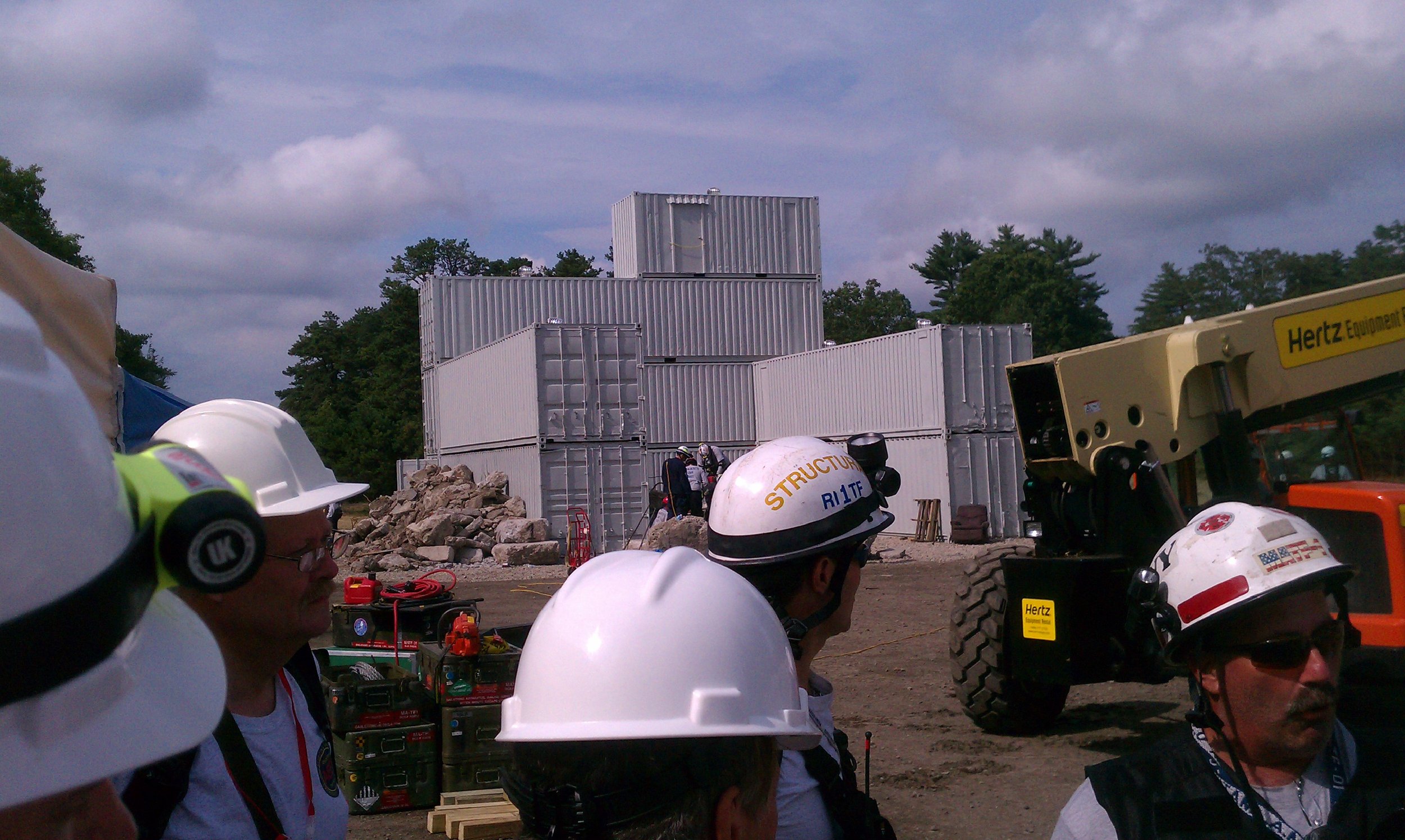
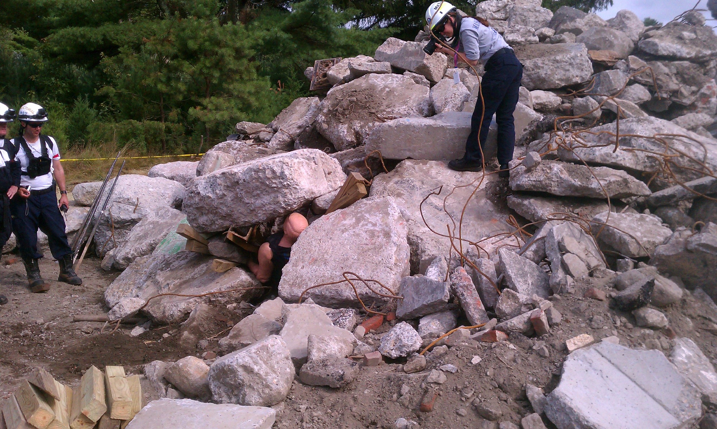
AEER-TF7 is trying to understand how to properly inspect damaged buildings after an extreme event. We inspected and filled out ATC forms at 4 different buildings. These forms require comments such as "percent damaged" (this may be area of damage - or - cost of repair/replacement, and if cost could it be more than assessed value or property? Broken windows in a distressed area may account for 50% of the assessed value of property but only 5% of the area of damage, etc). Also, we discussed what types of damage should be red and not yellow - since many of us used placards differently.
It was a very succesful event for us second responders.
Comparison of International Existing Building Code 2012 versus the Rhode Island State Rehabilitation Code
At the request of the Building Code Standards Committee of the RI State Building Code Commission, the Structural Engineers Association of Rhode Island (SEARI) Building Code Subcommittee created this document. Erik Nelson and Ethan Tirrel of Structures Workshop created this document with the help of David Odeh and other members of SEARI's Building Code Committee. It compares and contrasts the basic structural provisions of the current Rhode Island State Rehabilitation Code 2002 (“RI SRC-1”) with the 2012 Edition of the International Existing Building Code (“IEBC 2012”). The IEBC 2012 code will be replacing the SRC-1 code in 2013. Comparison of RI Rehab Code SRC 2002 vs IEBC 2012 Final
The purpose of this document is to provide an overview of the two codes and major changes to building structural design provisions that would occur if Rhode Island chooses to adopt the IEBC 2012 to replace the Rehab Code.
Objective Beauty and Fazlur Kahn
Last week, Structures Workshop was recommended for a very small project to a new client by the daughter of the great structural engineer Dr. Fazlur Kahn, Yasmin Kahn. This was a great honor for us to be recommended by Yasmin, also a structural engineer and prolific writer. I found this picture of them:  After learning about this, I started thinking about Dr. Fazlur Kahn and how much he contributed to my profession but also to the skyline of my hometown, Chicago. I was mesmerized as a child living in the northern suburbs of Chicago by glimpses, on clear days, of the John Hancock and Sears Tower. I wondered to myself if those memories contributed to my desire to one day become a structural engineer. I wanted to learn more about Dr. Fazlur Kahn and recently bought the book Engineering Architecture: the Vision of Fazlur Kahn which was written by his daughter Yasmin Kahn. I am reading it currently and it is a terrific book. To my delight, I have something in common with Dr. Fazlur Kahn. When he was 29, in 1958, and living in East Pakistan, two of his favorite books were Will Durrant’s Story of Philosophy and George Santayana’s The Sense of Beauty. I was about the same age when I read the The Sense of Beauty. It was 2001 in my case, and I was working at Thornton-Tomasetti in New York City and taking Philosophy classes at the New School at night. I remember The Sense of Beauty well – it was much easier than the other readings required for the Philosophy of Aesthetics course I was taking, and much better in many ways. This was a time when I thought beauty was objective – it just needed to a part of Plato’s archetypal forms. Since architectural beauty consisted of form and extension (today what we call proportion), then it is independent of subjects (unlike smell, taste, sound, touch). Form could be part of “the thing in itself” (Kant’s Noumenal World as opposed to his Phenomenal World of mere appearances – i.e. Plato's Cave). I thought that if the beauty was related to form, then it could become objective and viewed within Schopenhauer’s “will” (as opposed to representation). Another way to consider it objective is to say that beauty is part of Carl Jung’s “collective unconscious” (that is, beauty being a part the unconscious brain which is shared by all). Then, saying that something is beautiful (or ugly) can be universally and collectively accepted as fact (if form and extension have independent realities from our selves). I may have changed my view on this over time, but even so, I believe the Sears Tower and the John Hancock are objectively beautiful - and it is thanks to Dr. Fazlur Kahn.
Breaking Records in 2012
Structures Workshop is looking good in 2012 having completed 71 successful projects to date. Thank you to all our great clients! Here is a snap shot of our company from the beginning to now...

Manifesto for Growth Part 4
07/2012 Published “Manifesto for Growth Part 4” in Jule 2012 STRUCTURE Magazine. See this blog to comment on specific numbers. 1207 Manifesto for Growth Part 4
Can Engineers be Replaced by Robots?
For robots to be programmed to do engineering design, they would first be fed all the code information. That is easy, but AI would need to be amazing if it were to compete with humans on design (unrelated to codes and science). We are not there yet, and likely not for 50+ years or more.
Science and the building codes provide minimal information that is helpful to solve a particular problem. This is obvious to me as a practicing engineer so I get surprised when asked by some “what do you mean the code allows flexibility”, or “how can you say the code is of little importance”, or “I don’t understand you when you agree that the code is huge in content but will never help solve 95% +of problems we face”. Allow me to explain why engineering has little to do with codes (yes the code and science portion can replace engineers - but that is a small part of us).
“But they (computers) are useless. They can only give you answers.” (P. Picasso)
There are engineers (mostly academics who think wrongly that we are applied scientists) that actually believe structural engineering is just about stress and strain - (ie. about science). Let me respond to the main question about how engineering decision making is not procedural and can not be within codes by asking another question...
What do codes say about designing a simple steel beam?
Codes tell us not exceed 0.9 Fy Z for moment checks and something else for shear and that is about it. Codes do not say anything about the following...
what is an optimum spacing of beams?
how do I weigh economy vs efficiency -in other words should I use a lot of the same beam or optimize every beam for diff spans
should I consider camber and how to evaluate cost of camber vs increase size of beam without camber
constructability - should I make sure the girder is as deep or deeper than the beam even if the girder is a small span
should I evaluate the vibration of the beam
should I allow for shear tabs instead of double clips angles at the ends to save money in the details
while I am designing a beam to girder connection of the same depth, should I verify the connection works with a double cope by doing shear rupture and block shear calcs
should I verify the studs should be a max of 1 per foot, or go to 2
should I size the beam to be not composite
how do I evaluate costs of studs, etc
do I feel comfortable with a 1" deflection even if the code allows it for this 30ft member or should I stick to my arbitrary 0.75" I made up
should I evaluate the ponding of the concrete and add additional dead load when the beam deflects
is a wide flange the best solution for this or should I consider a channel instead
I decide for this beam I am unhappy about a previous job where I cambered the beam 1" and the tolerance the fabricator is allowed increased that to 1.5" and the SC connection provided some rotational restraint at the connection, so the camber didn't come out and those damn studs were actually sticking out of the top of concrete at midspan - so I am not going to camber that much again!
I don't trust the code deflection criteria and invent my own
what is my min percent composite action or max stud per foot or min length to use camber, etc
when is it a good idea to just optimize a beam for efficiency (code stuff), if I was designing the smallest possible beam it could have 3" of camber and 4 studs per foot!
should I use ASD or LRFD, does it matter, when does it matter and how or should I stick to my old ASD 89 green book and say to hell with 2005 and omega factors
what should I use as a max live load deflection when supporting CMU or Brick walls, L/600 or L/900 or ?
why am I designing steel in the first place, should we consider concrete or wood or ??? for this beam
am I comfortable assuming this beam is braced to 1.5" metal deck (parallel) or and should I check lateral torsion bucking with the wet concrete loads
should I assume that there is a true pin at the shear connection, or is there some rotational stiffness there. If so can I get relief from not meeting the code live load deflection criteria – sure why not.
can I assume the beam is fully braced if the top flange if supporting a wood framed floor with joist hangers and how do I evaluate whether a joist hanger can brace my steel beam effectively
why did I just check shear yielding when shear yielding never ever controls the shear strength of the beam, what a waste of time but this was something I learned in school, so I will procede to check rupture, etc ,etc
do I need to check block shear of a beam web when the cope is less wide than the dist to the bolt line
what should I be optimizing when design a beam and how do I prioritize efficiency, economy, connectivity, constructability, deflection camber and stud count
etc etc
I can go on this forever! The code says nothing about these questions. So my point is - even in the design of a simple beam, the code (or computer or Robot) plays a small role! If we extend that to the infinite number of problems we face than we will see the code (programming code information) is of importance on a small fraction of problems. So again...the code helps a little but for the most part we are on our own.
Robots will take the 80% of the codes and science part of engineering soon, and already have to some extent, but not much beyond that. Humans can just decide to choose wood instead of steel and for no reason whatsoever.
Humans create the questions to answer too, not just answers to questions.
Near-completion of the Duxbury Crematorium Building
See pic below of the near-completion of the Duxbury crematorium we designed:

What We See Depends Mainly on What We Look For
What we see depends mainly on what we look for. [John Lubbock, British banker, politician, naturalist and archaeologist]
If this is the case, what precedes this? What should we look for? This is why experience is so important in engineering. Determining what to look for is about prioritizing things we should look for and things we should ignore.
To know what to ask is already to know half. [Durant summarizing Aristotle]
Since engineering, like art, is the conscious use of skill and creative imagination, in addition to the ability to sift through many parameters, the only way to create a solution is to ignore things we can ignore and spent time on the things we need to spend time on. The only way to do this is to actively look for things that matter on our projects.
MIT Class Visits Fabricator
My MIT steel class visits Auciello Iron Works ...
Manifesto for Growth Part 3
06/2012 Published “Manifesto for Growth Part 3” in June 2012 STRUCTURE Magazine. See this blog to comment on specific numbers. 1206 Manifesto for Growth Part 3 pt
How do we improve our codes?
There are too many useless, confusing, burdensome, and disproportional provisions in our building codes. Useless provisions are those that are redundant or those provisions that are obvious. Confusing provisions are usually those that are overly prescriptive and difficult to understand due to excessive descriptive language. Burdensome provisions are those that are inappropriate and unnecessary for a particular structure but are required none-the-less. Disproportional provisions are those that are unnecessarily exact and not proportional to the assumptions and uncertainty inherent in structural design. How do we address this problem? Are we trying to perfect our building code far beyond our practical needs of providing safe structures? If so, how do we stop? http://structuresworkshop.com/blog/2011/10/16/9-improve-the-codes/
The Truth of Structural Design
There seems to be a progression of understanding as one designs structures. At first, as college students, we have well defined analytical techniques that appear objective and clear (there is truth). Later we learn this idea of structural design is naïve. What we do is not clean. As the years go by, there is an improvement of the design of structures which combines the simple objective science with more complex subjective decision making requiring sound judgment (heuristics). There is not truth anymore, what is left is "good enough". Problems encountered by the structural engineer are complex and nuanced and require experience and judgment to better sift through the multiple design ideas. If there was a progression in the mind of a structural engineer, I think it is similar to the one that the philosopher Friedrich Nietzsche wrote about in “Twilight of the Idols” (see MSC article). While Nietzsche was generally referring to raising the human spirit to a higher level, it is similar to my experience, going from 1 to 6, as a structural engineer over the fifteen years:
1. The ”truth” of structural design – is attainable for the sage, the pious, the virtuous man.
2. The “truth” of structural design - unattainable for now, but promised for the sage, the pious, the virtuous man.
3. The “truth” of structural design - unattainable, indemonstrable; but the very thought of it - a consolation, an obligation, an imperative.
4. The “truth” of structural design - unattainable? At any rate, unattained. And being unattained, also unknown. Consequently, not consoling, redeeming, or obligating: how could something unknown obligate us?
5. The “truth” of structural design - an idea which is no longer good for anything, not even obligating - an idea which has become useless and superfluous - consequently, a refuted idea: let us abolish it!
6. The “truth” of structural design — we have abolished. What world has remained? The apparent one perhaps? But no! With the true world we have also abolished the apparent one.
Thus, we have abolished truth in practice even if we pretend it still exists in school. Good enough is enough in practice (i.e. a good enough design decision = a correct answer). That doesn't make it easy, “good enough” is actually very hard. It is apparent in this progression the great extent to which the individual engineer can influence the design. I have found that the design of structures is less dispassionate and logical than I used to earlier in my career. There are no clear-cut answers to the complex and diverse problems we face. This is not to diminish the role of analytical tools to assimilate knowledge of phenomenon, it is just that it is simply not enough.
(E Nelson, portion of MSC Twilight of the Idols)
Published “Twilight of the Idols” Modern Steel Construction Magazine
Manifesto for Growth Part 2
05/2012 Published “Manifesto for Growth Part 2” in May 2012 STRUCTURE Magazine. See this blog to comment on specific numbers. Structure Mag-May 2012 Note: Part 8 should be "Kick Ass" (or "Kick Butt"), but the editors of STRUCTURE changed it to "Be Aggressive" unfortunately.
A Recent Day, Smelly Braced Frames
Engineers have to straddle many worlds. We may find ourselves one day designing steel connections, then meeting on a new job to discuss appropriate structural systems, then doing some BIM modeling. As we grow into project managers we may find ourselves writing emails and attending meetings possibly more than doing engineering calculations. We use our judgement more and more to know where to start a problem and what to ignore. There are no typical days. I had a day recently where one morning I designed all the braced frame connections on a job and then in the afternoon attended a project review at an architectural college. The student project consisted of spreading toothpaste on the wall and discussing how smell should be incorporated more into our built world. That is right, smell - and objects should contain smell. For some reason at that moment, it made sense. I thought about what the brace frame connection smelled like that I designed that morning. Not sure why, but I thought of that premade potato salad with that overly smelly mayo/mustard dressing.
Dreams, Mistakes and Uncomfortable Decisions
I woke up at 3am today again. It was the same dream, or similar dream to what I have been having over the last decade. I forgot to check something. I missed something in the code or I missed something more structurally egregious. This latest dream was something that surprised me because I was actually wrong, I did check it! I came to work early to discover that I did check this beam for additional load due to this or that, so no big deal. Sometimes my dreams help me, I get a sort of eureka moment and I am better able to tackle such and such problem. Other dreams are harmful, and they make me nervous and anxious and I can’t get back to bed. There are two main themes to these dreams: (1) Mistakes, whether real or imagined, and (2) Uncomfortable Decisions. Uncomfortable decisions are by far the most common of my dreams. These are engineering decisions that are made without the best understanding of how the part or system will perform (very common daily decisions when unique details or structures are developed). This is why engineering is a profession. We need to pull things out of a hat sometimes and live with them. Part of the anxiety of a structural engineer is that we are solving problems that never existed before, we are inventing something new. Yes, physics doesn’t change, but that is about the only thing that doesn’t. Every building has traits that no other building in the world has, and have we verified everything? Of course not. But have we verified everything we know how to verify? After all the calculations are applied, we still have to make a decision about whether it should be built a particular way or be changed. Eventually we have to say yes, “no exceptions taken” and live with it the rest of our lives. Crazy things get built and amazing engineers are the creative force behind all of them. How many structures out there do we lose sleep on? Maybe 2-3 per year on average?