21: Draw 1 to 1 Scale

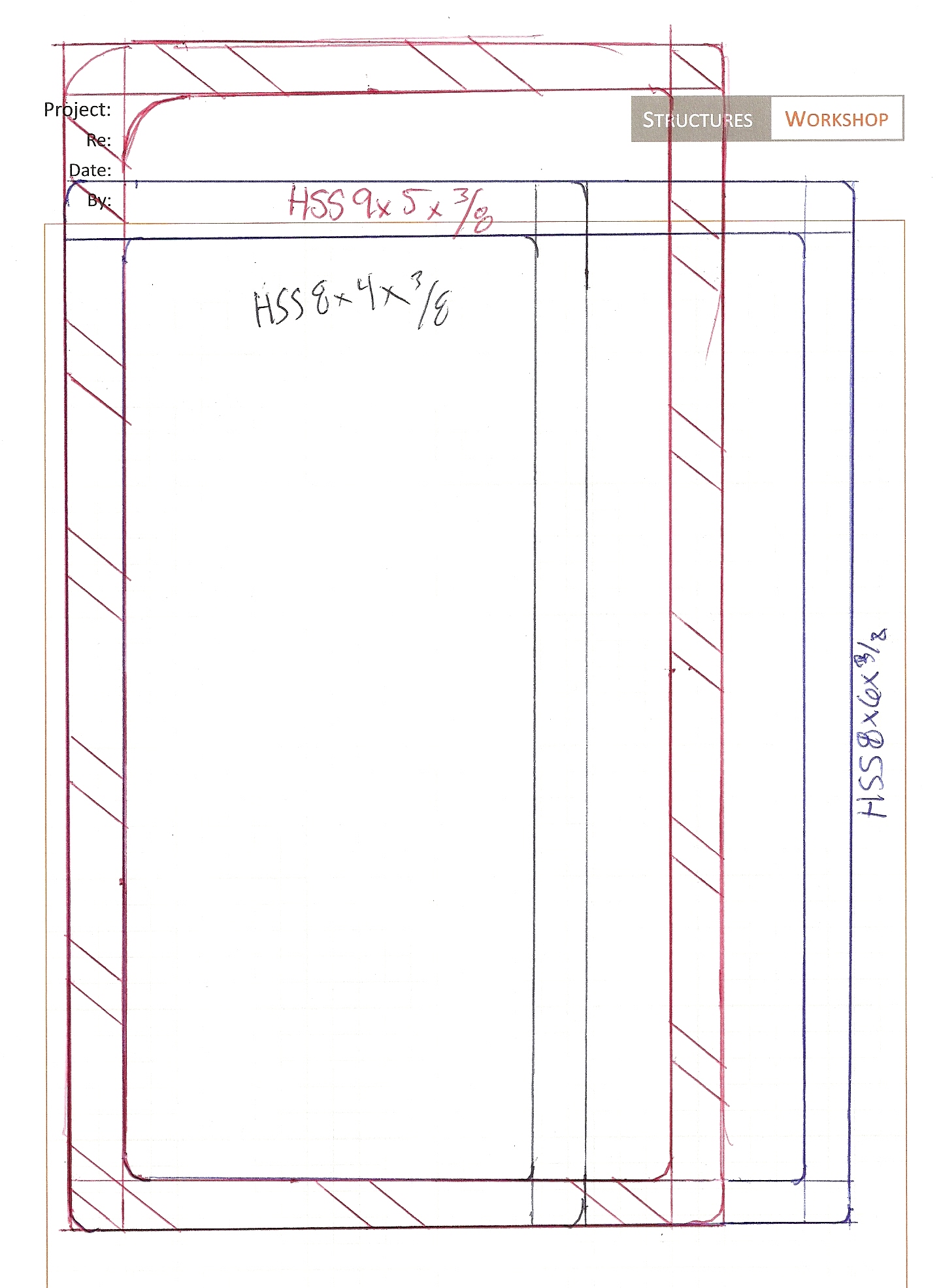
Plato believes what is central to the production of beautiful artifacts is one’s ability to understand the nature of measure (what we now may think of as proportion).  The engineer, according to Plato, must know the nature of measure or proper portioning of structures (artistic as well as scientific).  “Basic to any art, is the art of measure without which there can be no art at all.  For to know the proper size of a column, proportion of a window, the proper organization of language in a poem, is to command the art of measurement.”  Measure then for Plato, is essential to quality and is the fundamental principle that defines quality.  “There are accomplished men, Socrates, who say…the art of measurement is universal, and has to do with all things.” (Plato, Statesman 285b)  So if we think we succeeded in the proper form by creating something well proportioned, how do we know we are right?  How do we judge quality? Drawing 1 to 1 will help you make a better design decision on a particular component of a project.   Try drawing a 6x6 wood post on paper with the joist hanger, or a L4x4x5/16 steel framing angle with bolts to scale.   See if the bolts will fit and get into the code on bolt length (shank, threads, TC bolt tips, etc).   Drawing 1 to 1 will help you better understand proportions and with that, you will be able to use your intuition on the member size.

Here is an example of something we do in the office (comparing HSS members for columns on an 8 1/2 x 11)...

22: Buy Samples of Typical Structural Components

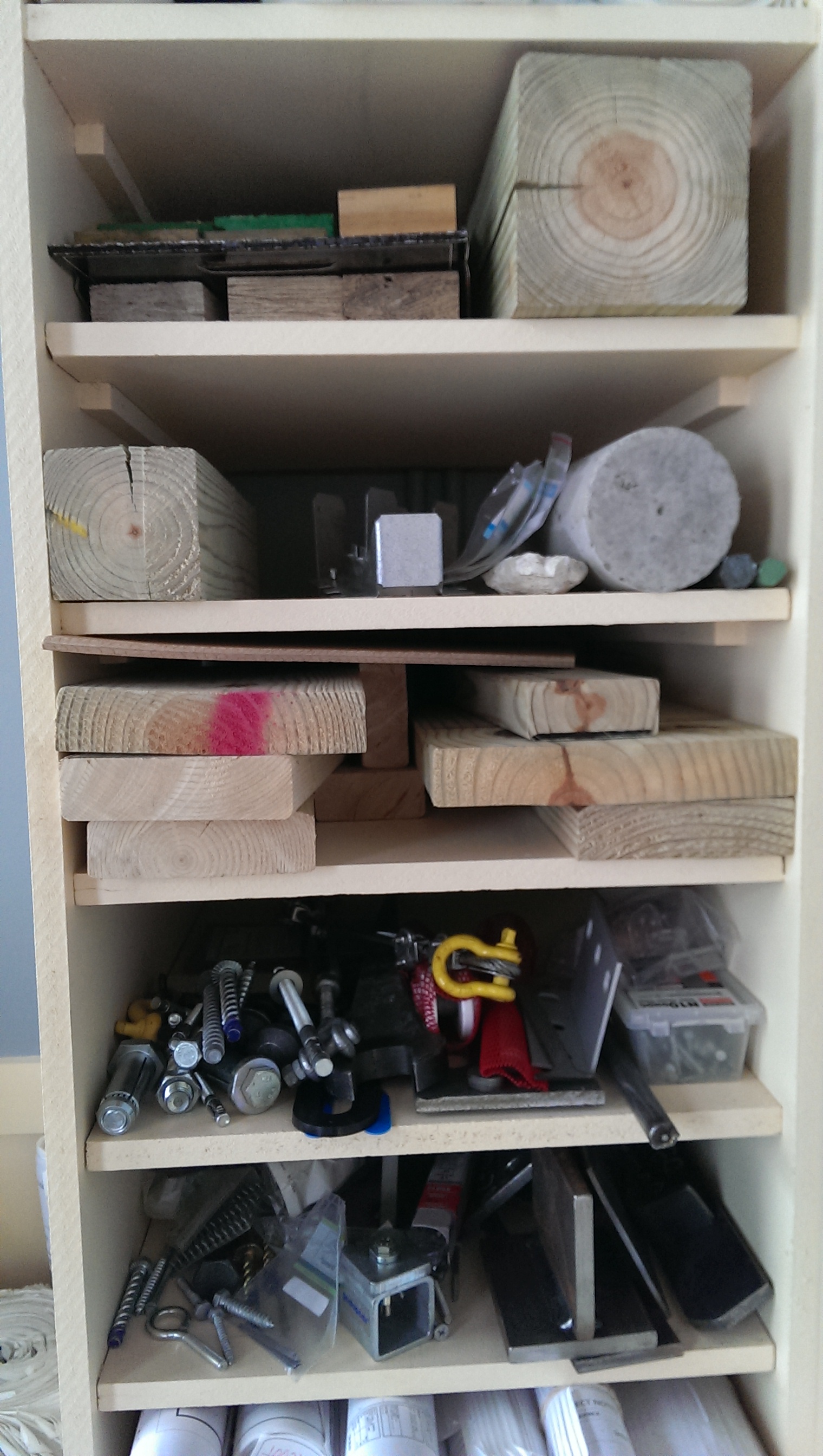
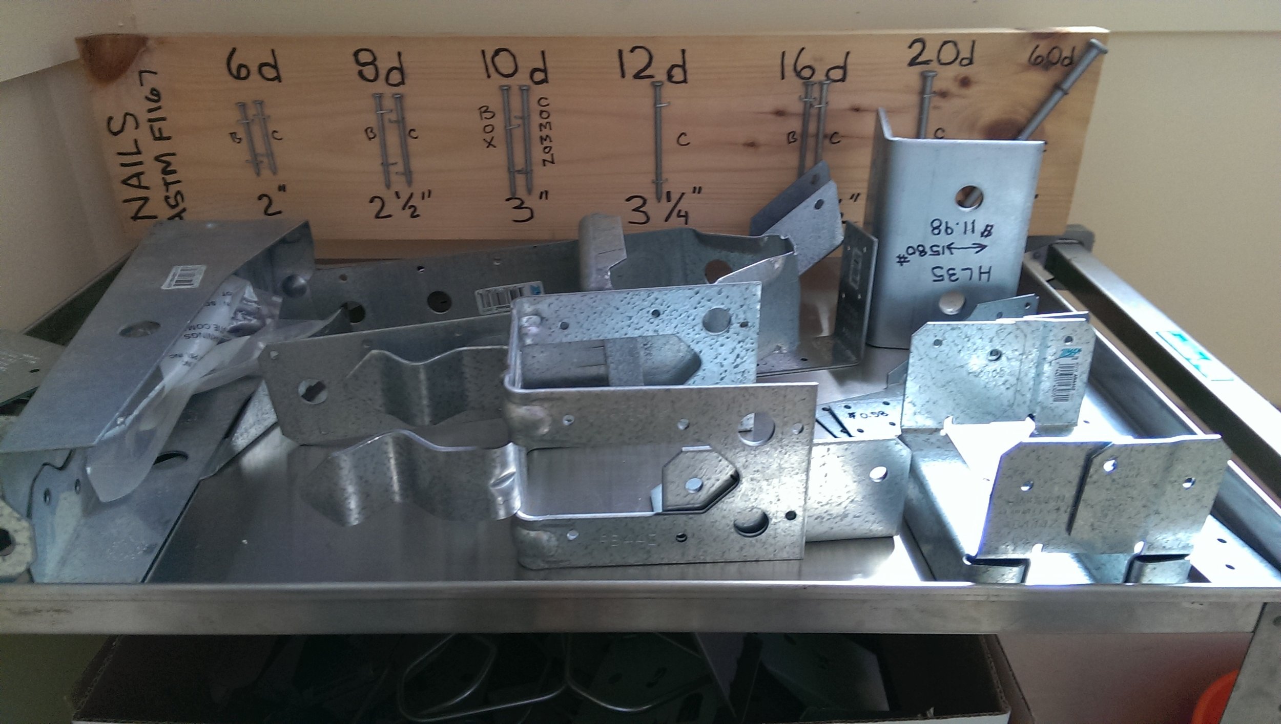
Go to Home Depot and buy structural components (and ask a fabricator/builder).  These items should be in your office while you design on the computer.   Having the material in your hand is the best way to proportion members later on the computer.  I recommended:

  • Wood Sizes (2x4, 2x6, 4x4 and 6x6 minimum, 1 foot length is fine)
  • Joist Hangers and Hurricane Ties  (Several Sizes)
  • 8" CMU (1)
  • #3 and #4 Rebar (1 foot length is fine)
  • An Expansion and Epoxy Bolt
  • Also ask a local fabricator for a foot of a W12x19
  • Shear Tab and Clip Angle  (5" Wide x 3/8 tab and a L4x4x3/8 angle,1 foot length is fine)
  • 3/4 dia A325N and A325-TC and 7/8 dia A490 bolts
  • Ask a concrete inspector for a 8" dia. concrete cylinder.
  • Get all the typical nails and screws (8d, 10d, #12 etc)
  • Etc

2013-07-02 13.43.20

Display these proudly in the office for all engineers to see.    These real samples are vital to be able to make informed structural design decisions.

2013-07-02 13.43.07

2013-02-21 10.19.48

23: Build Physical Models

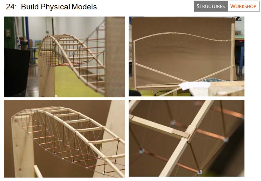
The computer will never replace the importance of a physical model out of cardboard, balsa wood, paper, glue, etc.   Architects build these all the time, we should too.

A design can be borne by art and uncertainty more than by science and certainty.   Isler created the thin concrete shell, a pillowcase shape, when he viewed burlap hanging over rebar.  The artist Kenneth Snelson developed the tensegrity by playing with sticks and strings.   The artist, Ai Wei Wei created the bird’s nest form used for the Beijing National Stadium for the 2008 Olympics by looking at one.  Bucky Fuller created the geodesic dome through sculpture and play.   He fooled around with stuff like triangles made out of spaghetti, not math.   The inventor Theo Jansen is the master of amazingly lifelike kinetic sculptures without math or science.  Math and science rarely contribute to the creation of the design (there are very few exceptions).    So why are we engineers not making stuff in school?   Who knows!

24: Feel and Flex Materials with Hands

Mathematical abstraction or physical laws are secondary to the primary feel (direct apprehension) and intuition of structures.   If you don't believe me, please read from our greatest engineers like Peter Rice’s An Engineer Imagines, Eduado Torroja’s The Philosophy of Structures, or Pier Luigi Nervi’s Structures (or Maillart, Torroja, Eads, Eiffel, Schlaich, Isler, Sobek, etc). Pier Luigi Nervi, one of the greatest structural engineers of all time, put it this way in has seminal work Structures (1956):

The pre-eminence given to mathematics in our schools of engineering, the purely analytical basis of the theory of elasticity, and its intrinsic difficulties persuade the young student that there is limitless potency in theoretical calculations, and give him blind faith in their results.  Under these conditions neither the students nor teachers try to understand and to feel intuitively the physical reality of a structure, how it moves under load, and how the various elements of a statically indeterminate structure react among themselves.  Today everything is done by theoretical calculations.  That student is rated best who best knows how to set up and solve mathematical equations... the mastering of structural knowledge is not knowledge of those mathematical developments which today constitute the theory of structures.  It is a result of a physical understanding of the complex behavior of a building, coupled with an intuitive interpretation of theoretical calculations.  [Nervi, 1956]

Nigel Cross, widely recognized as the leading figure in design research and teaching, summed up the importance of intuition this way in his book "Designerly Ways of Knowing" (2006):

Conventional wisdom about problem-solving seems often to be contradicted by the behavior of expert designers. But designing has many differences from conventional problem-solving.   Empirical studies of design activity have frequently found intuitive features of design ability to be the most effective and relevant to the intrinsic nature of design.  [N. Cross, 2006]

The way we think and feel about structures is more important than the abstract mathematical models or analytical techniques we use when solving problems.  Hardy Cross, our brilliant developer of the moment distribution method, once said:

Design involves sound judgement as well as stress analysis; and judgement is more important.  [H. Cross cited in Addis, 1990: 72]

I recently read an article on "The Genius of Steve Jobs" by Walter Issacson (Oct 30, NY Times) regarding the importance of intuition:

Steve jobs success dramatizes an interesting distinction between intelligence and genius.  His imaginative leaps were instinctive, unexpected, and at times magical.  They were sparked by intuition, not analytic rigor... he didn't study data or crunch numbers but like a pathfinder, he could sniff the winds and sense what lay ahead...when he  wandered around India after dropping out of college, (Jobs said) "The people of the Indian countryside do not use their intellect like we do, they use their intuition instead.   Intuition is a very powerful thing, more powerful than intellect."  [Issacson; NY Times Oct 30, 2011]

25: Don't Not Do It

“Just do it” from Nike is fine but it seems to be about finishing something you need to finish, not necessarily because you want to finish ("Just do it" is similar to avoiding procrastination).  So that isn’t enough.  “Don’t not do it” is about doing something you want to do but are afraid (worried because it is different, or maybe slightly embarrassing, or risky, etc).  It may be already finished or easy to finish but you are scared.   These are the things you need to do.   If you purge these mental roadblocks, you will benefit yourself.  You will never be “better than the rest” if you don’t allow yourself to complete something because of worry or risk – you will be the rest.  Don’t be the rest.  Don’t not do it.

"Action is a great restorer and builder of confidence. Inaction is not only the result, but the cause, of fear." [Norman Vincent Peale, author]


26: Take a Welding Class

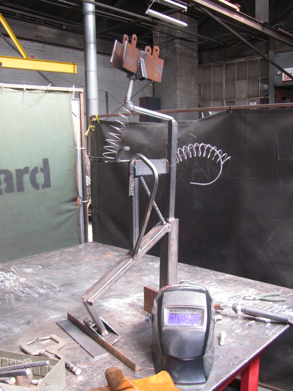
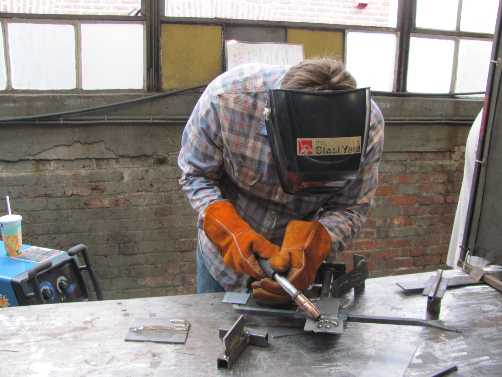
Why should engineers weld?   Because we design welds, and actually doing welding will help us understand and possibly design them better.  We need to understand the tools and the lingo (for example, saying "MIG" is more common than than engineer's GMAW). Here is the MIG welding machine:  The gases, argon and CO2, in the GMAW method create the shield to protect the weld wire from the atmosphere.Try finding a local workshop or welding class in your area.   Use an oxy-acetyline torch to cut through steel or bend steel, then use grinders to cut or smooth the edges.   Use a steel chop saw and sander, or a sand blaster to clean the mill scale.  Weld joints together using stick or MIG welding, adjust the voltage and wire speed to determine how to lay down quality welds.  Weld butt joints, t-joints, even flare bevel groove joints to determine which method and electrode orientation is best.   Create a sculpture, add and weld pieces to it.  Even bolt members together or learn how tap plates (drill holes and add threads).  If possible, use a plasma cutter and add letters to your sculpture and cut curves.

Here is a alien-robot I created at a recent welding workshop...

Here I am practicing GMAW:

Here is a jig I used to be able to cold-bend a piece of 1/2 bar...

I learned that welding poorly is really easy, and welding well is incredibly hard.  You won't be a welder after a couple classes, but you will certainly understand welding a bit better, and with this understanding you will become better at designing and inspecting welds.

27: Sketch Poorly and Sketch Often

Drawing quick sketches is essential to being able to make informed engineering decisions.  Drawings help us determine which elements are relevant and which may be safely ignored.  These daily hand sketches are needed to help us make subtle discriminations about proportion, member orientation, constructibility, connectivity, etc. So we need to sketch and sketch often, but do we need to sketch well?  (For this debate, well = pretty).  Does the sketch need to be nice looking with straight lines and perfectly to scale?  No.  Or should they be those cool architect type with soft and purposeful squiggly lines?  No, don't be cool - that is a waste of time.   Also don't show hand drawings to anyone where you focused on making them pretty instead of making them clear and useful.  Should they be on fancy black paper?  No.  They can be on any paper and with any pen.

The sketch can and should look like a 6 year old's drawing.  If you are better at drawing, of course, don't degrade your sketch by following this advice - but if you are average, don't be intimidated by others who waste their time making pretty sketches.  You need to sketch anyway, and all the time, constantly.  This is the most important action we do.  Sketches should only meet one criteria - they are to be useful to you and your team to communicate a design and to help with decision making about the design.  Feel free to sketch well as a hobby - by all means - add water color even, but for daily engineering, sketch poorly and sketch often.

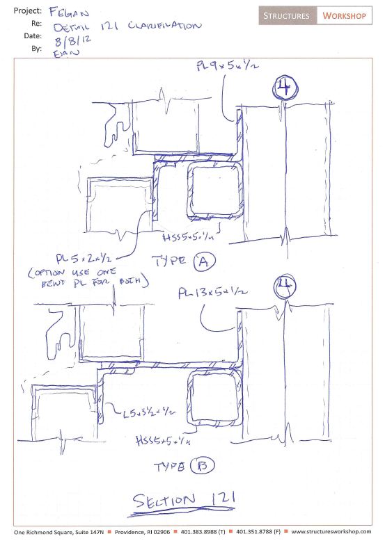
Here is a sketch I did today that is too pretty but serves as an example of what we should constantly be doing prior to, or along with, using the computer...

28: Email Well (Less Words, More Pics)

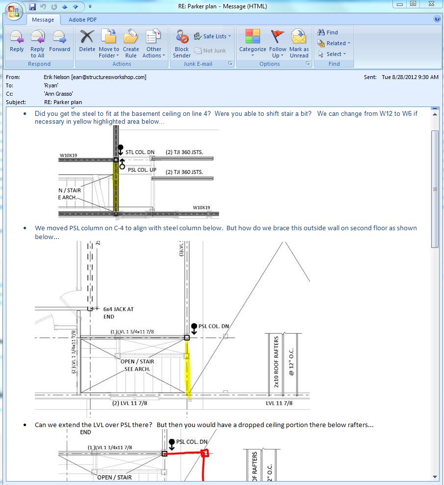
As a design community we email poorly - way too many words, not enough pictures/sketches/details/screen shots.   It is still the coordination tool of choice today, but there isn't one way to email.  Add lots of screen shots! Here is a bad email...

"Erik,  On grid line 8 east of wall A, near the dining room wall, there is a post that needs to be moved 6" to the north.   Remember, north is to the left on the PDF set you have.  Sincerely, Bobby Cantemail"

Here is a good email...


29: Stand instead of Sit

Add a standing desk to the office (or ask for one!).   Engineers typically spend 80%-90% of their time in an office sitting in front of a computer.  Not much we can do about this, but adding a standing desk to the office as an optional work location can help mix things up...where you can go and work while standing and stretching. 2013-10-26 11.17.25

We added this work station with a desk with adjustable height   We also have the option of leaning back on this FOCAL bike seat we bought - which is between sitting and standing (like the comfortable kitchen counter at home).   As an aside, this should be obvious by now in 2013, but all engineering work stations should have 2 monitors each a min 23 inches (24/27 preferable) so you can work on BIM on one side, calcs on the other.


Lincoln Center Theater

Just stumbled upon some great pictures of our Lincoln Center project.  We were the erection engineers for this long span roof truss.... lct3-progress3[1]

This included determining each pick, how to hang entire truss on existing wall, reinforcing of existing roof for construction loads, reinforcing existing retaining wall for the crane loads, rigging, full construction sequencing etc.

LCT_3[1]

Here is one portion of our 30+ drawings...

pick 12

Final Building (Long Span Truss above building)...lct3

In the foreground you can see the green roof that is hyperbolic.   We were also involved in that project (Arup was EOR) back in 2009.  We designed all the connections for that roof.

IRC 2012 / IBC 2012 / ASCE 7 10 - Why did wind speed increase 30mph?

One big change from IBC 2009 / ASCE 7 05 is that wind speeds in IBC 2012 / ASCE 7 10 are now "ultimate" values and associated with risk category and have increased about 30%.  For example, in the typical risk cat II, wind speed in Providence is now 133 mph (instead of 100 mph before).  That increase is counter balanced by new load combinations that reduce the wind load factor within the ASCE 7 USD/LRFD combos from 1.6 to 1.0 (or from 0.8 to 0.5) depending on the combination used.   Since wind pressure is proportional to velocity squared, it turns out that in Providence, wind pressure did increase a little overall, since wind speed increased 133mph^2/100mph^2 = 1.77, but the load factor in the ASCE 7 10 combos only went down from 1.6 to 1 (so wind pressure after doing the load combinations did still increase about 10% or 1.77/1.6 in Providence).   It also depends a little on type of load combinations.  For Boston, the wind in Cat II went from 105mph to 128mph, and 128mph^2/105mph^2 = 1.49 which is less than 1.6.   So for Boston wind pressure went down about 8% +/-, but in Providence it went up about 10% +/-.  Not a big deal but here is the problem... Believe it or not, our brilliant code writers are using different wind speeds now for the IRC and IBC codes.    The IBC has gone to an ultimate strength value to be used (LRFD) while the IRC has the old 3-sec gust data (based on ASD).   So it is Vult for IBC and Vasd for IRC - but both use ASCE-7 2010 as the reference standard.     Per IBC 2012 section 1609.3.1 you can get back to ASD values by multiplying the ult values by the square root of 0.6 (or 0.775). So, for Providence 133mph x 0.775 = 103 approx= 100mph which is what can be used in IRC/SBC-2 (this conversion is also necessary when comparing to others standards/triggers that are not updated).

Yes, this is going to lead to much confusion because load cases are now mixed up with load combinations.  Here is another problem - if I have a house and I choose to use the IRC/SBC-2 wind speeds (say 100mph based on Vasd), I better not use the ASCE-7 10 combinations - that is double dipping since there is already a 0.6W factor within the new ASD combos (instead of 1.0W).   So if you are using IRC wind speeds, you should use the old ASCE 7 05 load combinations - but that is no longer a reference standard!   Therefore, one option is if you are using IRC wind speeds, you can factor them up by 1/0.775 to get pressures, and then use the ASCE-7 2010 combinations.   What a mess!   I am planning on using Vult from ASCE 7 10 for both IBC and IRC for wind to avoid load combo confusion.

These code people are obviously not designers because this new code will lead to more confusion and more errors (and how would a building official understand this?  they don't see combos used,  only mph on drawings).   It was already unnecessary to go to Vult in my opinion, but then for IRC to not follow IBC is really strange.   Good luck with this!   My understanding is we are in a transition, and IRC will eventually adopt the same methods as IBC.

Single Plate Shear Connections with New Eccentricity

The following post contains several ideas that will form a future article in a magazine (by Erik Nelson and Doug Seymour),  therefore comments are welcome! ... In the 13th Edition AISC Steel Construction Manual, eccentricity was neglected for most conventional single-plate connections (shear tabs). Some of this practice was based upon the 20% reduction in bolt strength for end loading (a condition that doesn’t apply to shear connections).  As a result, the 14th Edition AISC Manual contains recommendations for accounting of the eccentricity in conventional single-plate connections. Now bolt shear calculations must include an eccentricity (typically half of the distance from the bolt line to the weld line).  This is an important change, since the reduction in bolt shear (and possibly bolt bearing strength) can be significant even for small eccentricities.

Consider the conventional single-plate connection with SSL holes illustrated in Figure 1.

1

The ICR method is used to account for the effect of the eccentric load on the bolt shear strength. For a number of common connection types and eccentricities, including the configuration of the conventional single-plate connection, the effective number of bolts for that connection, C, is given in the AISC Manual in Tables 7-6 to 7-13. The values published in AISC Manual Table 7-6 are useful, but the small eccentricities common in single-plate connections often fall below the entries in the table.

Since many conventional single-plate connections have a = 2 in. or 2½ in. (and a/2 values of 1 in. or 1¼ in.), we have prepared C values for these eccentricities for the convenience. The data is given in Table 2 with the additional information beyond that given already in Table 7-6 shown shaded.

2

The C values given in AISC Manual Tables 7-6 to 7-13 are determined using the strength predicted for each bolt group by that method, divided by the strength of one bolt under concentric load. The result is an equivalent number of bolts for the given bolt pattern, with the given load eccentricity, to be used in calculations.

In addition to bolt shear, this same C/N approach can be used to account for the effect of eccentricity on the nominal bolt bearing strength. Using C and N, the total number of bolts in the connection:

Rn,bolt = (C/N)  2.4dtFu                                                                            

The strength of the connection can be determined as the sum of the individual bolt bearing strengths.   For simple shear tabs with one line of bolts, eccentricity can still be ignored in bearing calculations according to the manual.  In fact, letting the bolts deform the material in bearing has the advantage of increasing the flexibility of the connection to reduce moment transfer.  This has bean confirmed by tests for single lines of bolts with small eccentricity.  For extended plates, the C/N method can apply and is simple to perform by hand calculations since C has already been determined for bolt shear.

You may notice that we left out the tearout portion of the bearing equation.  Unfortunately, we do not have a simple method of accounting for tearout in eccentrically loaded bolt groups of shear connections. In typical configurations of a single column of bolts, only one bolt may experience tearout, but it is not clear how to satisfy statics under eccentricity (horizontal components must sum to zero) when for example, the lower bolt experiences tearout and the upper bolt experiences bearing.  We recommend sizing the plate such that the edges distances are large enough so tearout does not control for extended plate shear connections.  There are likely more advanced methods to account for tearout, but any method must satisfy statics and equilibrium,  in addition to having a design with sufficient ductility to redistribute the loads.

Our QMA West Canopy Entrance is Erected

M. Cohen and Sons steel installed the West Entry to the future Queens Museum recently (Grimshaw Architects / Amman and Whitney / Capco).  The design is a seamless stainless steel cantilevered frame with a 1/2" thick edge on all three sides.  We were the structural engineers for the canopy and designed the canopy within a 1/16" edge tolerance by unhinging the stainless steel from the deflection of the carbon steel cantilevers. 25

Under thermal movements, the walls are designed to move with the contraction and expansion of the roof, so the walls were hung. This allowed the joint between the wall and the roof to be seamless.  Here is a portion of our BIM model...

Here is a Video

30

Arcade transformed to Micro-Apartments

We were involved in helping reshape the future of this iconic building...the nations oldest shopping mall into tiny lofts.   Here is a great recent article... http://www.architizer.com/en_us/

We worked with Northeast Collaborative Architects and developer Evan Granoff to add some headers, infill walls, a bridge, and other stabilizing elements to the Arcade.   The two upper floors will become 48 apartments between 225 and 450 square feet.

• Settings >> Advanced >> Code Injection >> Footer