On Sept 27, 2013, Erik Nelson will be speaking at the Structural Engineers Association of North Carolina annual conferance. For more info... http://www.seaofnc.org/Portals/22/Conference%20brochure.pdf
On Sept 27, 2013, Erik Nelson will be speaking at the Structural Engineers Association of North Carolina annual conferance. For more info... http://www.seaofnc.org/Portals/22/Conference%20brochure.pdf
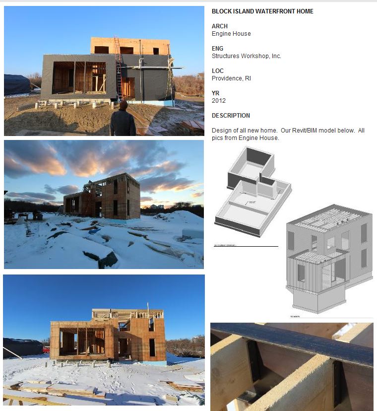
Here is are two picuctures of a house we designed in Block Island (pics from Design Builder - Engine House)...
![tumblr_mofnd7lfBa1r2n6jqo4_1280[1]](http://static1.squarespace.com/static/5b50dee412b13f916dbf6993/5b64a7fce0c9380bf64954f1/5b64a805e0c9380bf64956c9/1533323269377/tumblr_mofnd7lfBa1r2n6jqo4_12801.jpg?format=original)
![tumblr_mp5z356ypx1r2n6jqo1_1280[1]](http://static1.squarespace.com/static/5b50dee412b13f916dbf6993/5b64a7fce0c9380bf64954f1/5b64a805e0c9380bf64956cb/1533323269414/tumblr_mp5z356ypx1r2n6jqo1_12801.jpg?format=original)
One big change from IBC 2009 / ASCE 7 05 is that wind speeds in IBC 2012 / ASCE 7 10 are now "ultimate" values and associated with risk category and have increased about 30%. For example, in the typical risk cat II, wind speed in Providence is now 133 mph (instead of 100 mph before). That increase is counter balanced by new load combinations that reduce the wind load factor within the ASCE 7 USD/LRFD combos from 1.6 to 1.0 (or from 0.8 to 0.5) depending on the combination used. Since wind pressure is proportional to velocity squared, it turns out that in Providence, wind pressure did increase a little overall, since wind speed increased 133mph^2/100mph^2 = 1.77, but the load factor in the ASCE 7 10 combos only went down from 1.6 to 1 (so wind pressure after doing the load combinations did still increase about 10% or 1.77/1.6 in Providence). It also depends a little on type of load combinations. For Boston, the wind in Cat II went from 105mph to 128mph, and 128mph^2/105mph^2 = 1.49 which is less than 1.6. So for Boston wind pressure went down about 8% +/-, but in Providence it went up about 10% +/-. Not a big deal but here is the problem... Believe it or not, our brilliant code writers are using different wind speeds now for the IRC and IBC codes. The IBC has gone to an ultimate strength value to be used (LRFD) while the IRC has the old 3-sec gust data (based on ASD). So it is Vult for IBC and Vasd for IRC - but both use ASCE-7 2010 as the reference standard. Per IBC 2012 section 1609.3.1 you can get back to ASD values by multiplying the ult values by the square root of 0.6 (or 0.775). So, for Providence 133mph x 0.775 = 103 approx= 100mph which is what can be used in IRC/SBC-2 (this conversion is also necessary when comparing to others standards/triggers that are not updated).
Yes, this is going to lead to much confusion because load cases are now mixed up with load combinations. Here is another problem - if I have a house and I choose to use the IRC/SBC-2 wind speeds (say 100mph based on Vasd), I better not use the ASCE-7 10 combinations - that is double dipping since there is already a 0.6W factor within the new ASD combos (instead of 1.0W). So if you are using IRC wind speeds, you should use the old ASCE 7 05 load combinations - but that is no longer a reference standard! Therefore, one option is if you are using IRC wind speeds, you can factor them up by 1/0.775 to get pressures, and then use the ASCE-7 2010 combinations. What a mess! I am planning on using Vult from ASCE 7 10 for both IBC and IRC for wind to avoid load combo confusion.
These code people are obviously not designers because this new code will lead to more confusion and more errors (and how would a building official understand this? they don't see combos used, only mph on drawings). It was already unnecessary to go to Vult in my opinion, but then for IRC to not follow IBC is really strange. Good luck with this! My understanding is we are in a transition, and IRC will eventually adopt the same methods as IBC.
The following post contains several ideas that will form a future article in a magazine (by Erik Nelson and Doug Seymour), therefore comments are welcome! ... In the 13th Edition AISC Steel Construction Manual, eccentricity was neglected for most conventional single-plate connections (shear tabs). Some of this practice was based upon the 20% reduction in bolt strength for end loading (a condition that doesn’t apply to shear connections). As a result, the 14th Edition AISC Manual contains recommendations for accounting of the eccentricity in conventional single-plate connections. Now bolt shear calculations must include an eccentricity (typically half of the distance from the bolt line to the weld line). This is an important change, since the reduction in bolt shear (and possibly bolt bearing strength) can be significant even for small eccentricities.
Consider the conventional single-plate connection with SSL holes illustrated in Figure 1.

The ICR method is used to account for the effect of the eccentric load on the bolt shear strength. For a number of common connection types and eccentricities, including the configuration of the conventional single-plate connection, the effective number of bolts for that connection, C, is given in the AISC Manual in Tables 7-6 to 7-13. The values published in AISC Manual Table 7-6 are useful, but the small eccentricities common in single-plate connections often fall below the entries in the table.
Since many conventional single-plate connections have a = 2 in. or 2½ in. (and a/2 values of 1 in. or 1¼ in.), we have prepared C values for these eccentricities for the convenience. The data is given in Table 2 with the additional information beyond that given already in Table 7-6 shown shaded.

The C values given in AISC Manual Tables 7-6 to 7-13 are determined using the strength predicted for each bolt group by that method, divided by the strength of one bolt under concentric load. The result is an equivalent number of bolts for the given bolt pattern, with the given load eccentricity, to be used in calculations.
In addition to bolt shear, this same C/N approach can be used to account for the effect of eccentricity on the nominal bolt bearing strength. Using C and N, the total number of bolts in the connection:
Rn,bolt = (C/N) 2.4dtFu
The strength of the connection can be determined as the sum of the individual bolt bearing strengths. For simple shear tabs with one line of bolts, eccentricity can still be ignored in bearing calculations according to the manual. In fact, letting the bolts deform the material in bearing has the advantage of increasing the flexibility of the connection to reduce moment transfer. This has bean confirmed by tests for single lines of bolts with small eccentricity. For extended plates, the C/N method can apply and is simple to perform by hand calculations since C has already been determined for bolt shear.
You may notice that we left out the tearout portion of the bearing equation. Unfortunately, we do not have a simple method of accounting for tearout in eccentrically loaded bolt groups of shear connections. In typical configurations of a single column of bolts, only one bolt may experience tearout, but it is not clear how to satisfy statics under eccentricity (horizontal components must sum to zero) when for example, the lower bolt experiences tearout and the upper bolt experiences bearing. We recommend sizing the plate such that the edges distances are large enough so tearout does not control for extended plate shear connections. There are likely more advanced methods to account for tearout, but any method must satisfy statics and equilibrium, in addition to having a design with sufficient ductility to redistribute the loads.
Published "Socrates, How is Engineering Knowledge Attained?" in STRUCTURE magazine April 2013. See PDF of article below...
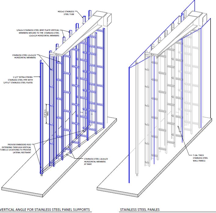
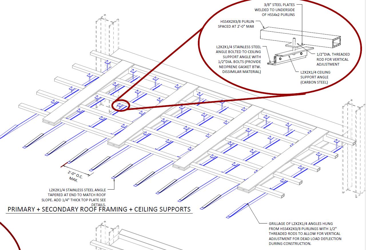
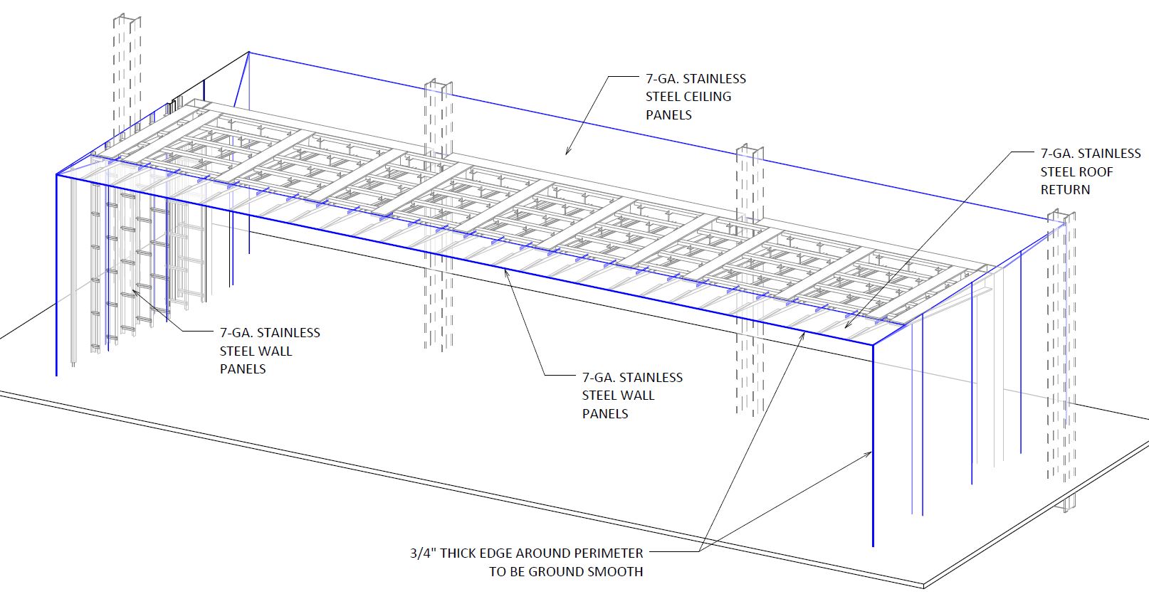
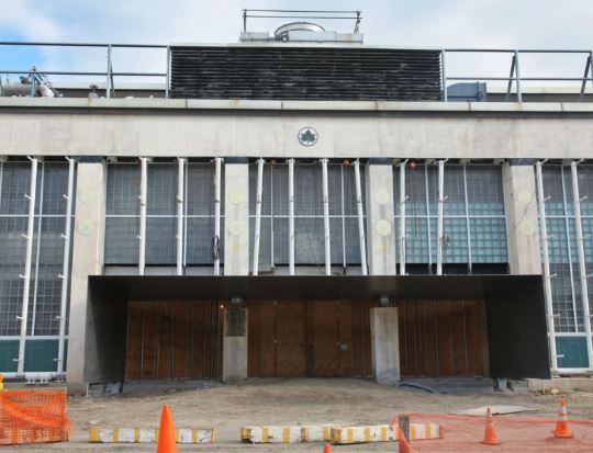
M. Cohen and Sons steel installed the West Entry to the future Queens Museum recently (Grimshaw Architects / Amman and Whitney / Capco). The design is a seamless stainless steel cantilevered frame with a 1/2" thick edge on all three sides. We were the structural engineers for the canopy and designed the canopy within a 1/16" edge tolerance by unhinging the stainless steel from the deflection of the carbon steel cantilevers.

Under thermal movements, the walls are designed to move with the contraction and expansion of the roof, so the walls were hung. This allowed the joint between the wall and the roof to be seamless. Here is a portion of our BIM model...
Here is a Video

We were involved in helping reshape the future of this iconic building...the nations oldest shopping mall into tiny lofts. Here is a great recent article... http://www.architizer.com/en_us/
We worked with Northeast Collaborative Architects and developer Evan Granoff to add some headers, infill walls, a bridge, and other stabilizing elements to the Arcade. The two upper floors will become 48 apartments between 225 and 450 square feet.
The steel is up on the New Rochelle Project...

In January 2013, Ethan and I published an article in MSC related to reducing the amount of expensive CJP welds and substituting fillets welds instead. We provided a simple table to assist the engineer and fabricator in using fillets instead of CJP welds...

See the following PDF for more info: Economical Steel Design (MSC)
Trusses are simply built out of triangles - and they are actually defined as such. Some member will be in tension and some members will be in compression (about half). The trick, and at times difficulty, is to determine which members are in tension and which members are in compression. We can simplify things by recognizing there are only two types of triangles in trusses. One that has two tension members, and one has only one tensions member (tension = rope, compression = wood in below image)...

If I extend this into a longer truss and simply replace the compression member with the tension member, we have...

Do you see the two types of triangle? Also as you can see, the bottom chord is in tension and the top chord is in compression. The trick to determining which diagonal or vertical member is in tension or compression, is ask if they follow the same curve as a hanging chain would between the two end points. If they do, they are in tension, if not, they are in compression.
This is a stable truss for gravity loads...

What is really interesting about changing out the sticks for strings when they are in tension, is the fact that the entire truss can now be folded! Check it out...

Think about how this can be extend to designing and building folding architecture, temporary construction, or tents etc.
Lamella structures are created using many pieces of the exact same member shape and connection. So 1000 pieces of something and stacked in a certain manner...

You can imagine it can get pretty big depending on the size of the individual beams and the quantity. Here a pic with my RISD class a few years back that we built together from sticks I cut in my basement and eye hooks to temporarily hold the pieces together...

I wrote about the physics of this system as well... Published “Infinite Load Path?” October 2007 Structure Magazine if interested.
For a arch to be prefect, it must be shaped such that it is in uniform compression. Basically the inverse of a hanging chain. So we can build what Robert Hooke describes in 1675 "as hangs the flexible line, so but inverted will stand the rigid arch". So, we can hang strings from a sheet of plywood, trace and cut...
 As the thin shell innovator Heinz Isler would say "One does not actually create the form; one lets it become, as it has to according to its own law". Also, this is an exceedingly complex mathematical shape called the hyperbolic cosine or catenary.
So we cut ...

Remove...

And build...

Here is how you can build the most excellent rectangle ever conceived...

You start with a square, and you use one edge center point as a centroid of the quarter circle as shown above. Then you can trace on top of this rectangle spiral growth rings...

You can introduce concepts of moment and equilibrium by building a simple balance beam...

The weights times the distances on each side of the fulcrum have to equal. I added nails at 1" spacings and use washers for the weights...works well. And it is fun for the kids (Anders and Kinan in background)... force times distance has to be equal on each side.

You can imagine a person hanging from a cable that forms a Y in shape between to cliffs. What are the forces in the cables? Well we can build this by adding a wight in the middle of a system, and measuring the cable tension by hanging other weights off pulleys like so...

The more weight you add to each end, the more shallow the cable gets. In other words, the more horizontal the rope, the more tension it contains. Can the rope be perfectly flat with a point load in the middle? The answer is no, you would need infinite cable tension! If cables are horizontal you have infinite tension, if cables are perfectly vertical, you have half the load carried.
What about uneven loading, or changes in cable angle like so?

The more vertical rope in this case takes more tension than the less steep rope, but why is that? For discussion (sum forces in X and Y).
Here are Plato's two perfect triangles from his seminal work "Timaeus" that can create the 5 platonic solids (which are according to him form the elements of earth, air, water, fire ...)

They are worth having as objects in the bookshelf to use and demonstrate how to build platonic solids, geodesic domes, tensegrity structures, etc. Also they can be used to for statics class to demonstrate simple trigonometry (45/45/90 and 30/60/90 triangles), as well as x and y components of force vectors in statics.
Comparing braced frames to moment frames, is like comparing triangles to squares...
 The square can easily deform and requires rigid joints if used as a lateral system to resist wind/seismic...
 The triangle can only deform if the member itself shrinks or extends axially (along length) - which is difficult to do significantly (PL/AE). The square with rigid joints does not need to deform axially, it simple needs to bend and it will translate. So moment frames are about 20 times more flexible than braced frames (+/-10). To make a moment frame into braced frame, simply add a diagonal...

You can make four strips of wood, say 1" wide by 1/8" thick. Take a pair and tape the middle together, take another pair and only tape the ends. Feel the difference in stiffness...

The one you one tape in the middle will act as two separate beams. The one you taped at the ends will act as one beam with double the thickness. How much stiffer will the beam that is taped at the ends be? Since deflection is proportional to moment of inertia, and I is proportional to thickness cubed, it will be 4 times more stiff! Two cubed is eight, and 1 cubed times 2 members is 2, and 8/2 = 4. It will be double the strength and 4 times the stiffness - just by taping the ends so it resists horizontal shear and acts as a composite beam. Go ahead and try this simple experiment.